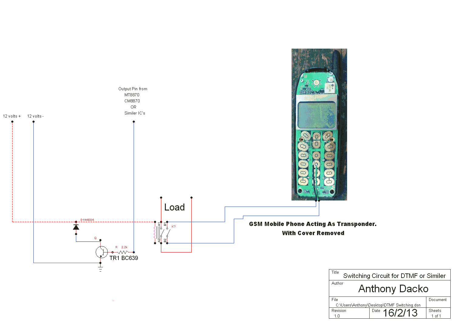
Welcome to this Schematic on how to use a mobile phone as a DTMF Transponder with call back when the relay is switched on.
1). I designed this Schematic to allow a Modified cell phone to be used as a transponder as I am using a Double pole 12 volts relay, This has one contact to the main load and one contact that can activate the one touch dial on the mobile phone so it can call back to me when the relay closes.
2). Like all my designs I use off the self components and give Technical support by e-mail with any thing to do with my designs I also tell you where to buy the parts.
3). The design is simple to build it is in three parts the first the Regulator Section then the DTMF Decoder Section then the relay Switching Section.
4). The Relay used is a 12Vdc coil 360R Rated 8A/230Vac, 8A/30Vdc. Order Code SW053 for Relay I used click here.
5 The Crystal is a 3.579545 Mhz you can get them from here order code CX027 Click here.
6). How the electronics works is like a lot of DTMF decoders a lot of them have know way of telling you they have switched on the relay or if the signal got to the decoder ok, In this simple schematic I have designed the One Channel Global remote DTMF to send back a notification signal this will work with any DTMF Decoder that has a Double pole relay.
7). Please note this is only to send back a notification when the relay has switched on this works by using one contact to activate the one touch dial or speed dial on the back up cell phone and the next contacts powers your load.
8). Now if you have all ready build your own DTMF decoder and would like to build this simple Notification into your own system then please do the parts are simple to get hold of they are all of the self components.
9). Now if you have build your DTMF decoder and want to have it send back a gsm signal then you don't need to add the DTMF Decoder below you just need to add the Switching Circuit below the schematic below.
Now we will look at how to modify a old cell phone for our Transponder see the information below on how to do this.
10). Now you have all the things you need to modify your cell phone first we will need to load the mobile number into the phone make sure you have the ringer set to silent all so one touch answer turned off and one touch dial or speed dial turned on.
Now say if you put your own mobile phone number in number 5 and connected the wire coming from the relay to number five on the circuit board then this will call your mobile phone when activated.
11). Now you will need to buy a Cell phone opening kit to get access to the phones electronics we are only interested in the pads under the phones keys see photo below.
12). You can get Cell phone opening kits from most electronic stores or shops or look on Ebay.
13). Now look at the pads you have an inside pad and outside pad solder one wire to the inside pad be careful the inside pad does not touch the out side pad and VS or you will get a short or bridge and you will need to use cleaning tools to try and fix it. .
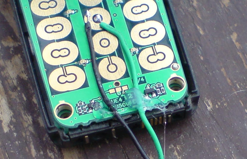
14). Now when you come to fix your wires to the pad put one wire in side the pad and using your soldering Iron push down on the wire this will heat the solder so it fixes to the pad do the same with the next bit of wire but connect this to the outside pad see photo below.
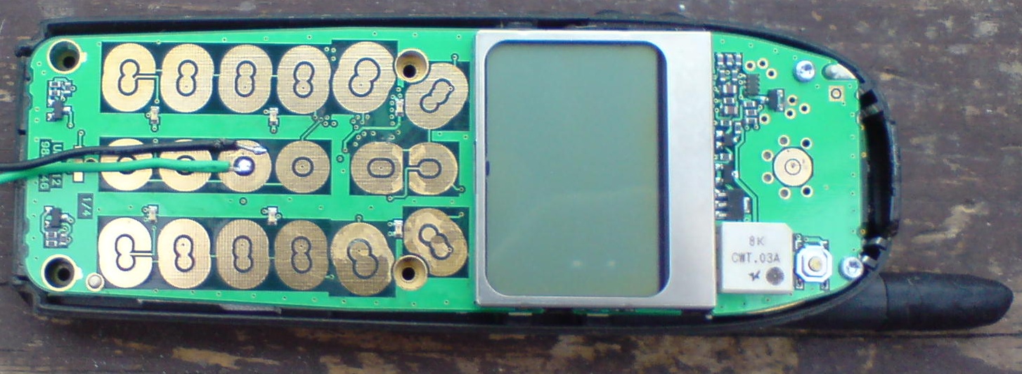
In the photo above you can see I have soldered the two wires to the in & out side pads of the modified phone in the photo above I used my Nokia phone as this was a better photo than the one I used before.
You may also want to add a little bit of hot melt glue to the bottom of the wires to take some of the stress from the solder contacts see photo below.
Any phone with touch button and one touch dial/speed dial will work.
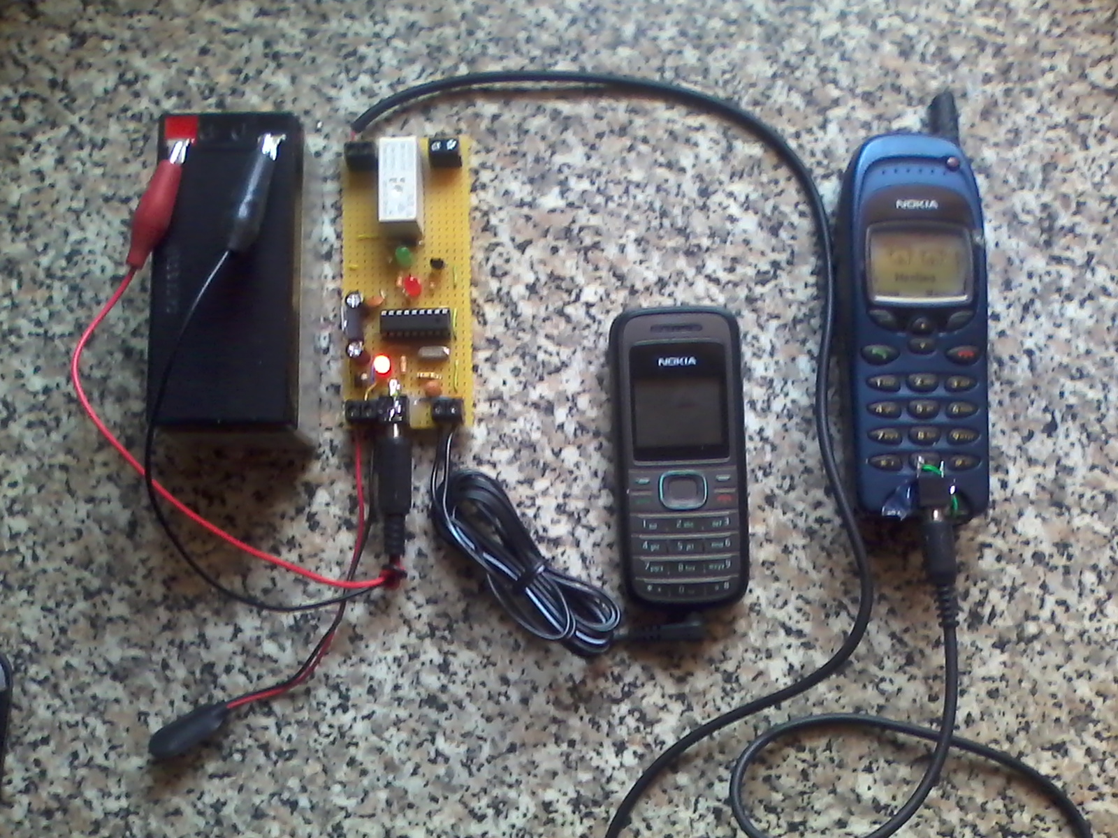
Items you will need are one mains operated timer switch to keep the mobile phone fully charged up.
![]()
Now in this Schematic I have
designed the Schematic to allow any DTMF devise to send a GSM signal back when
the Double pole relay is switched on.