Welcome to this very simple modification that allows you to hard wire your DTMF or any devise that you want to use by remote control, But don't want to run 240 or 120 Volts around your rooms.
Now if you would like to see the devise working then visit my You Tube Page here.
In the photo below you can see one of the devises in my loft space with cover left off for photo only.
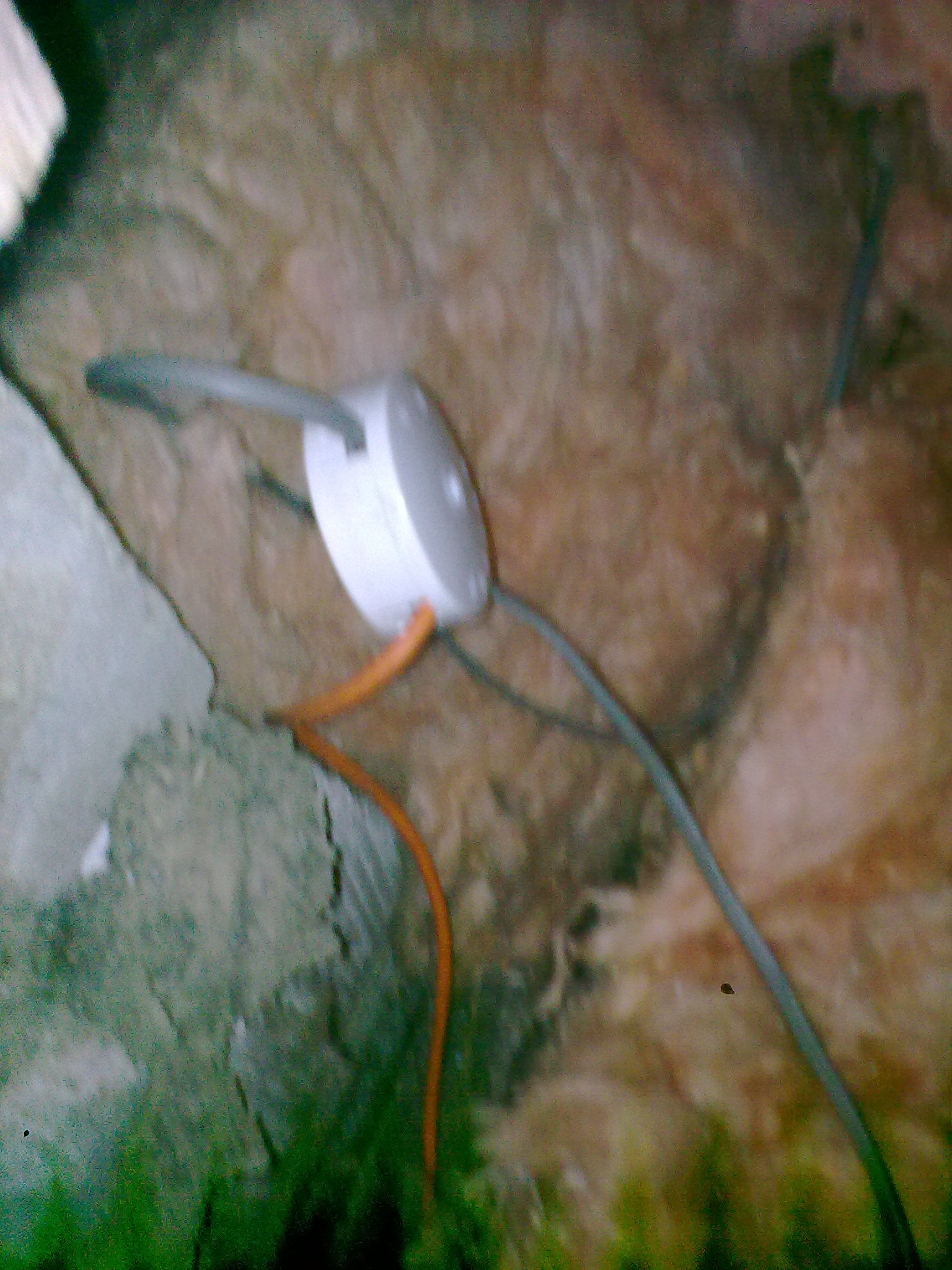
In the photo below you can see the white 12 volt cable and the orange 240 volt cable this is going to one of my lights in my home it by passes the on off switch.
I can turn the DTMF light switch on or off by global remote control or manual.
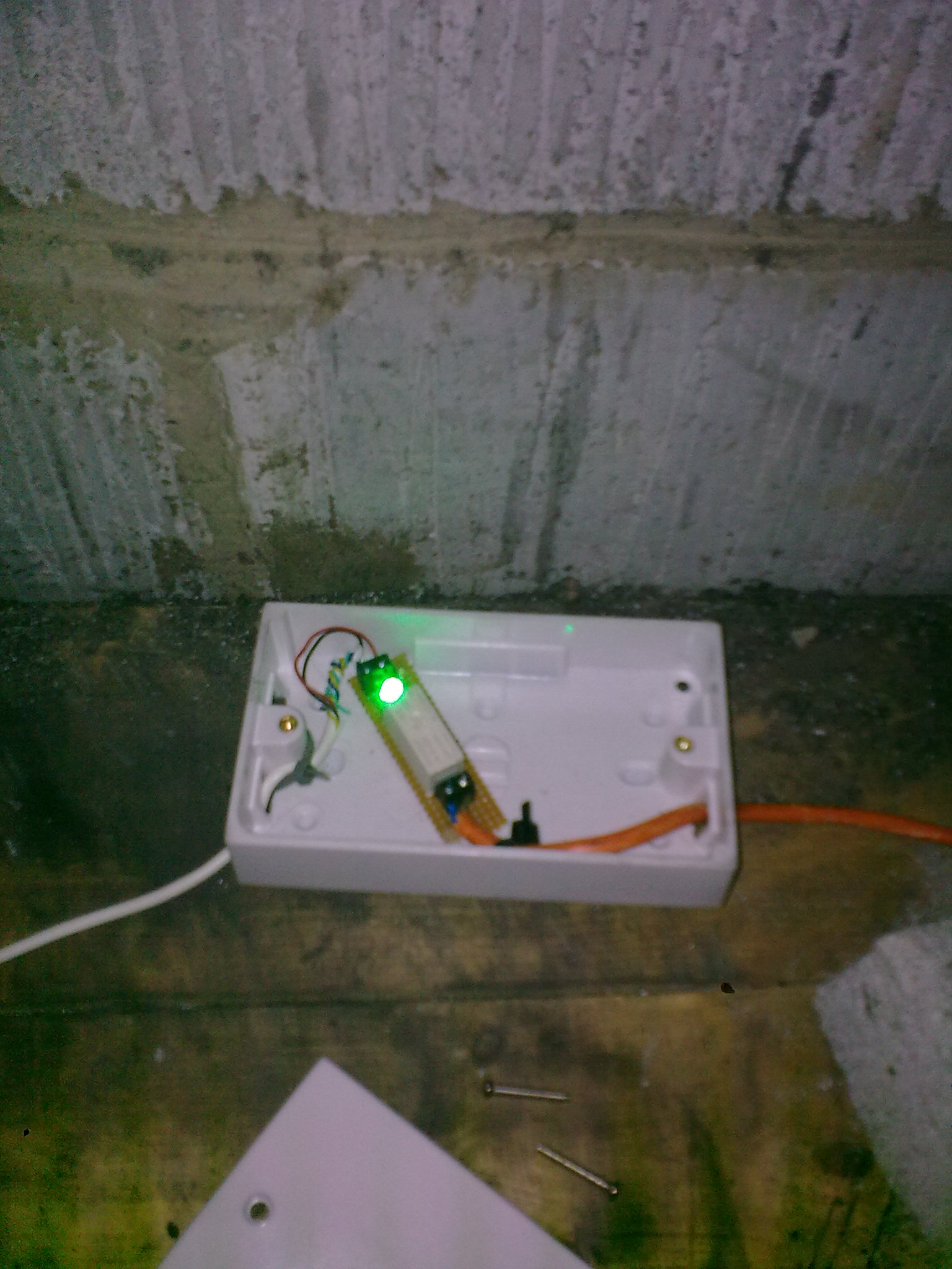
In the photo above this is in my loft space for the photo I left the cover off.
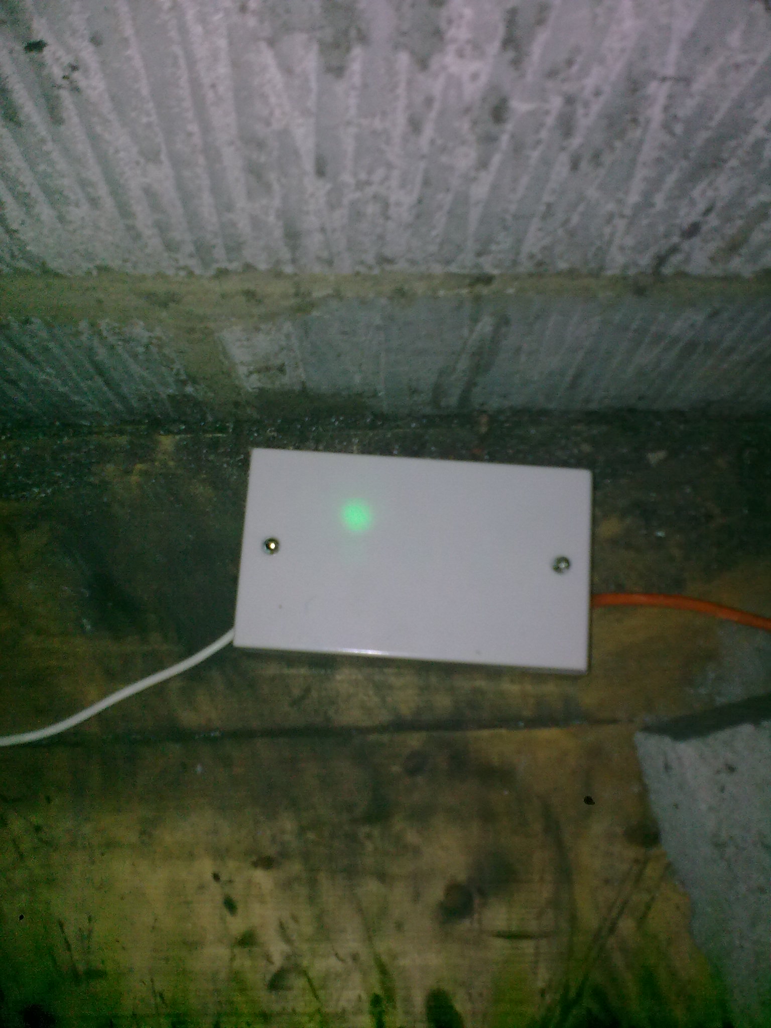
In the photo below I have put the cover back on to the box.
In the photo below I have used a junction box as I had to cut the electrical cable to make the modification.
All my lights in my home now can be switched on or off from any where in the world good for security.
1). I designed this very simple switch to allow your DTMF devise to be hard wired with a much lower voltage as most of us are not happy having 120 or 240 volts cables run around our rooms. This is a very cheap design to copy it is also much safer if you have young kids in your home or where ever you use the devise.
2).The simple design can find lots of uses in the home or work place it is nothing more than a simple low voltage switch that allows you to switch on higher voltages from a distance or with remote control devises.
3). In this design it is much better to use a 12 volt extension lead that carries only 12 volts only when the second relay is switch on it will allow the 120 or 240 volts to power your load the 120 or 240 volts lead will be shorter as it is connected to the mains socket.
4). This simple design may find many use's in the field of electronics, I designed it to work with my own DTMF decoder in my first design I showed you how to use radio waves in this design I will show you how to hard wire it up.
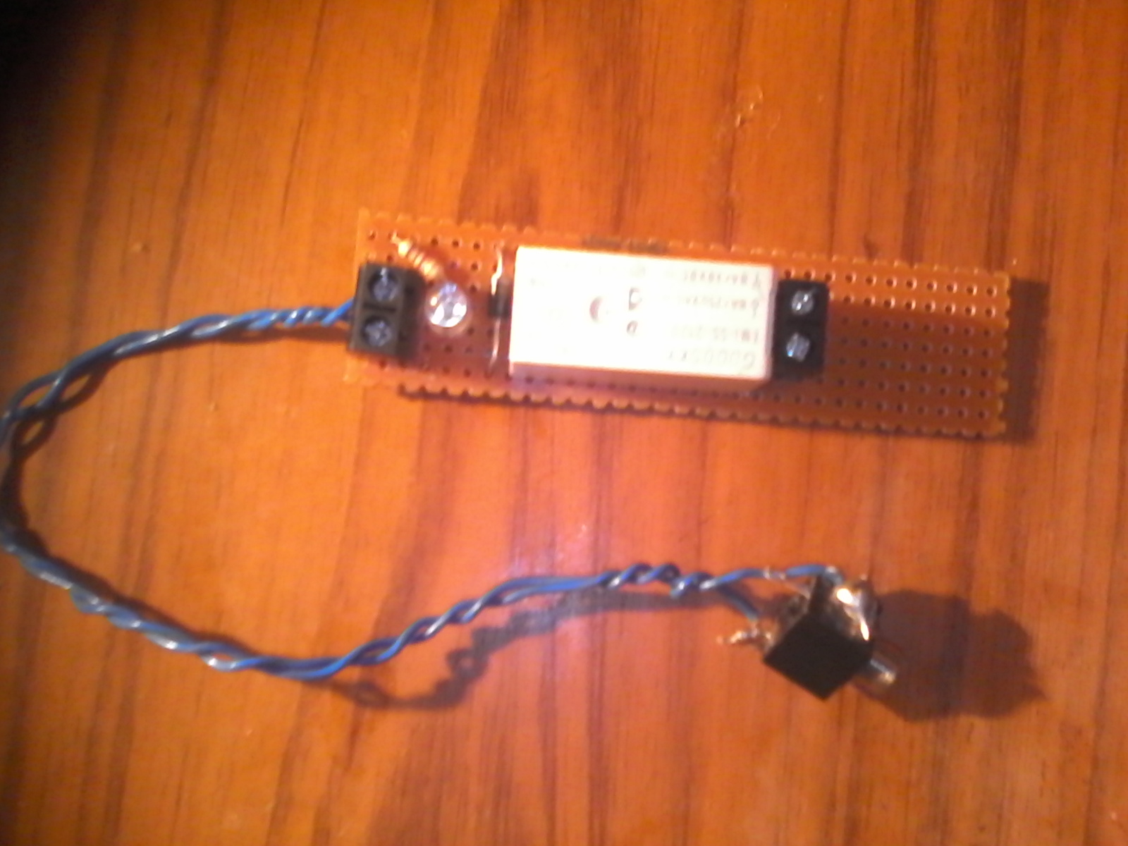
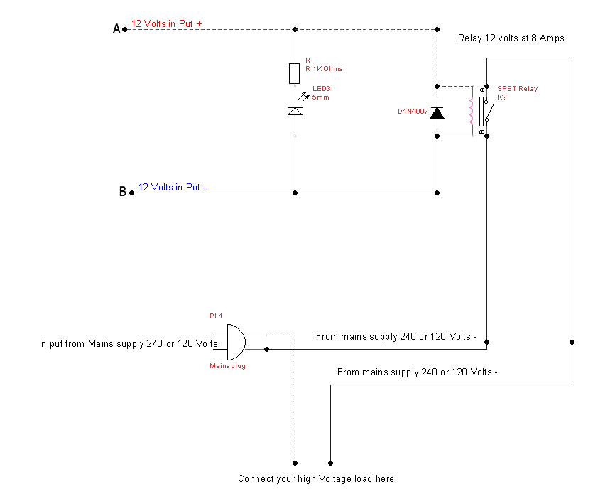
5). The circuit is nothing any more than a relay with a diode and resister also LED how you make your own is up to you but the Schematic diagram is below.
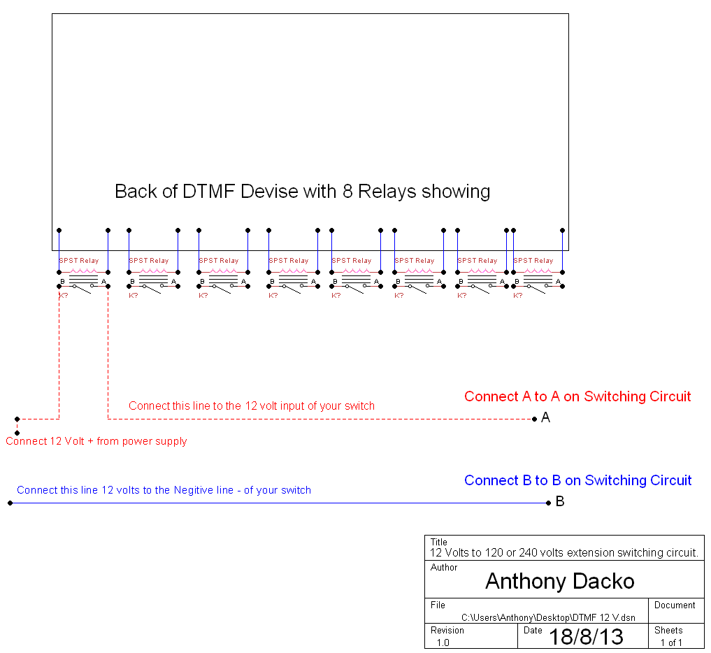
In the Schematic below you can see the simple switching circuit
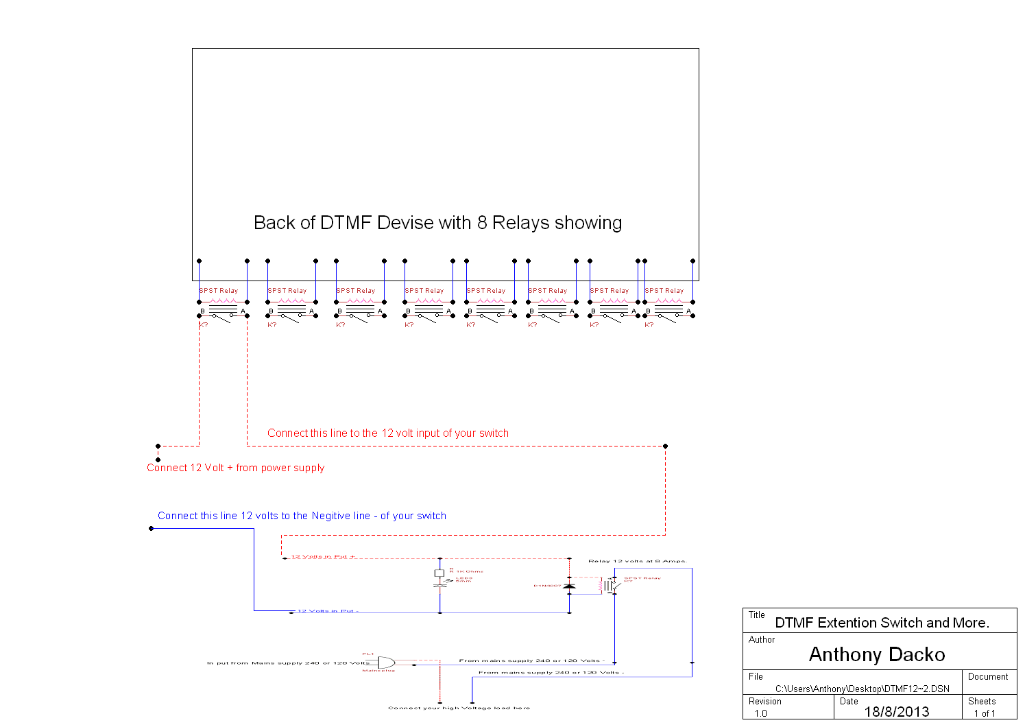
Here is how the Schematic looks when both devises are connected together below.
In the photo below you can see how to wire it up if you want to use your light on the Ceiling.
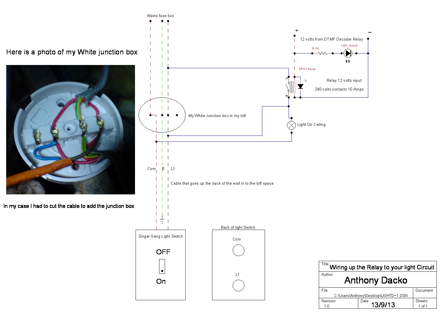
How the circuit works when the light switch on the wall is pushed down the light comes on as it is allowing current to flow into the light, but when the light is switched off this cuts the flow of current.
This simple modification allows any DTMF Decoder to by pass the main on/off switch and turn the relay on making the same contact but allowing the current to flow with the help of the relay to the lamp.
If you send your DTMF Decoder a command to send power to the relay and the light is off the contacts on the relay will close this is making a short cut for the current to flow in to the lamp and will switch it on or off by Global remote control.
Then if you what to turn your lights back on you must send the DTMF decoder the command to cut the power to the relay and the wall switch will work like normal.
6). Now you can have a long run of 12 volt cable from your DTMF or device's to your mains supply this is a safer way than running 120 or 240 volts around your home with cables the cable will only carry 12 volts.
7). Now when the input receives 12
volts the 1K Resister will limit the current to the LED this is just to let you
know the power is getting to your devise ok. The Diode is a Rectifier 1N4007 you
can use a lower number like 1N4004 this is there to stop reverse Polarity damage
or EMF.
8). Now when power is applied the relay will switch the Negative line of your
mains supply to your load the Positive line must be connected all the time. The
relay is acting like a automatic switch.
9). Now when you send your DTMF devise a command to close a relay as soon as the relay is closed this will send 12 Volts along the extension wire to your switch and Power the second relay and turn your load on or off.
10). You will need to put the devise into a plastic box as the box will have 120 or 240 volts switching from the second relay.
11). Please keep in mind the relay needs to be able to switch 120 or 240 volts at it's contacts the one used in the prototype is this can handle a switching current of 8 Amps.
12). Now make sure the contacts you use also can handle the current as my relay is 8 Amps my contacts should be 8 Amps or higher if you are using lower currents then that is fine as long as you do not go over the current rating of the contacts or relay.
Please note if you have any Problems building any thing I have designed please do e-mail me and I will do what I can to help. Anthony@anthony-dacko.net