How to stop your Land Line DTMF Decoder Activating on every incoming call on the same Line as your Phone, Answer Machine or Fax Machine.
1). I have had a number of requests to design an electronic circuit so a Land Line DTMF decoder will not take the incoming call if some one was just phoning you or if they wanted to leave a message on your Answer phone or send a fax.
2). The problem with most Lind line DTMF Decoders is they take the incoming call after a few rings, Now if the DTMF decoder needs a code and it is not send in time it will cut the caller off.
3). This is why you often need a second phone line when using DTMF Decoders on a phone line, Now having a second phone line is not a good idea as it cost more money the design here will allow any DTMF Land Line to work on the same phone line as every thing else on it with out taking every incoming call.
4). This type of problem can be over come very easy, I will be showing you with my own DTMF Decoder as I have all ready done the modifications.
5). I have come up with this idea as it is simple to build cheap and the best of it is it can work with any form of DTMF Tones and switch the main Land Line DTMF Decoder in or out of the phone line.
6). This way it makes it possible to have your normal phone, Answer phone or fax on the same line with out the problem of the DTMF Decoder Answering every incoming call at the same time.
7). This idea will not only save you from needing a second phone line but also has the benefit of adding even more security to your system alone with the DTMF Decoders own 4 pin code.
8). In this design I used the AS1186KT - 4/8-Channel Telephone Activated Relay Board from Quasar electronics as my Land Line DTMF Decoder. click here.
9). Please note it does not matter if you have a different Lind Line version of DTMF Decoder as we are only turning it on or off by remote control to switch it in & out of the phone line.
10). The parts for this design should not be a problem as they are off the shelf components
Now we will look at the Schematic diagram below of the single channel on/off DTMF Remote control.
11). Now how the simple circuit works is very simple when the single channel DTMF is not activated the relay is out of circuit so no power is going to the relay of the first DTMF Decoder.
12). Now as there is no power going to the second Lind line DTMF Decoder your Land Line Phone, Answer Phone or Fax work like normal on the same line as your DTMF Devise no need for a second phone line.
13) Now say I want to turn my Second Land Line DTMF Decoder on
all I have to do is phone my Cell phone connected to my one channel global
remote and wait till it auto answers the incoming call and press on my mobile
phone key * and activate my first DTMF Devises Relay, Then this will connect my
phone line to my Second DTMF Line in put socket.
14). Then as the single channel has latched on I can disconnect the call to the
mobile and phone the Land Line DTMF and enter my four pin code then turn on
or off my devises.
15). Now after I have send my on or off commands all I have to do is wait for my Second DTMF Decoder to disconnect me as it is on a timer or I can disconnect my self by cancelling the call.
16). Now all I have to do is disconnect from my Land line then phone the Mobile and press on my mobile phone # and the relay on my single channel DTMF will switch the circuit out again allowing my Land Line Phone, Answer Phone or Fax to work like normal again.
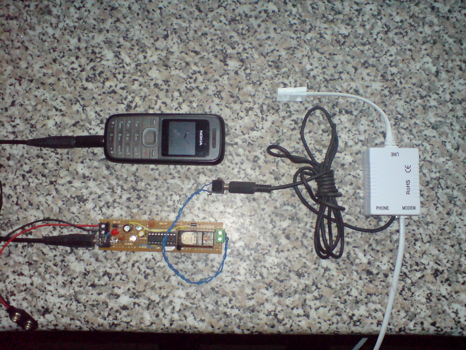
17). Parts list Now most of the parts you can get from any electronic shop or Store you can get the MT8870 from e-bay here. The Crystal is a 3.579545MHz Quartz Oscillator Crystal click here. The Transistor is a BC 639 order it from here.
Mobile Phone used was a Nokia 1208 with Auto Answer on it.
Welcome to the second part of the modification for the Phone line DTMF Decoder Switch,
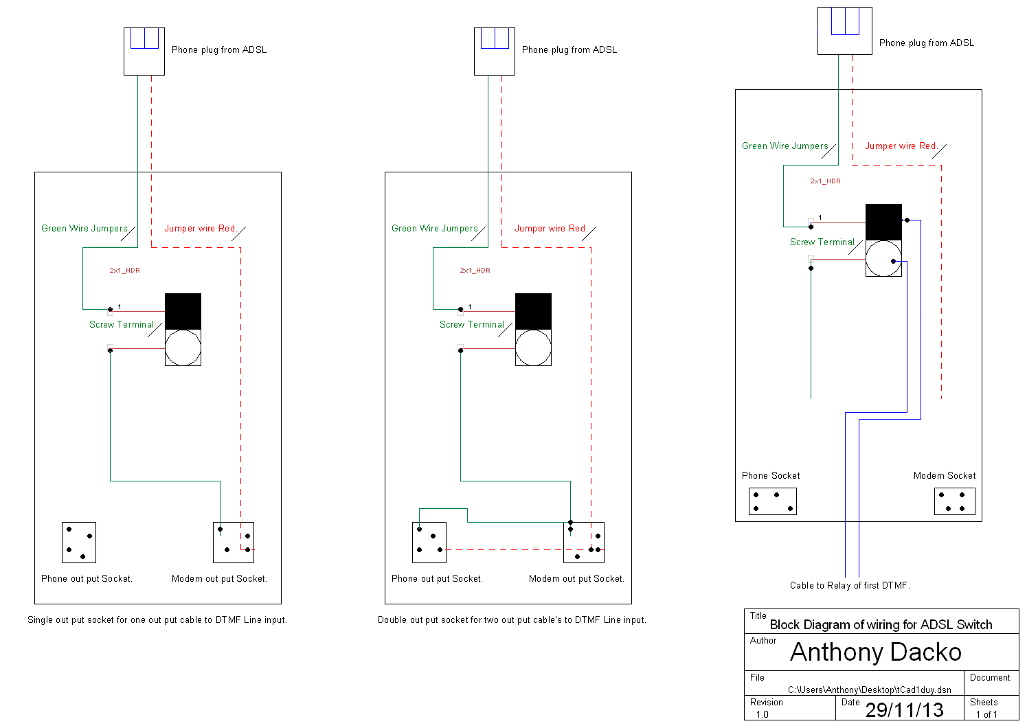
Please note at the bottom of the page I have given the block Diagram how to wire up the filter switch.
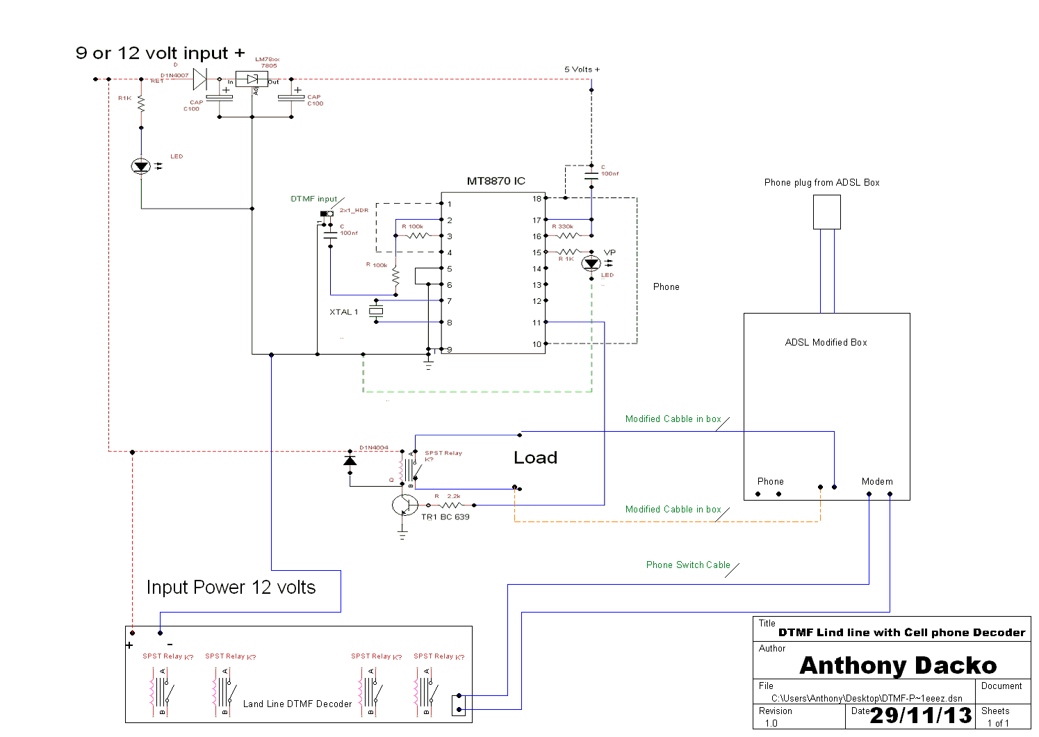
18). Here we will be doing a very simple modification and using a small ASDL Filter box, I came up with this simple modification down to me not wanting my own DTMF Automation system Answering on every in coming call.
19). The benefits of my simple design here are you don't need a second phone line so saves money, Also it won't Answer on every incoming call from any one so your Phone, Answer Machine or Fax work like normal.
20). The design makes it more difficult for any one trying to hack the system as it is turned on by remote control from a cell phone and DTMF Remote control it is only turned on for a very short time.
21). The cost of the design above was only about £10 or $10 to do the modification this is to buy the Filter box as it covers the UK Phone Connections and the USA Phone connections as well and more.
If you want to do this Modification then you can buy a simple ADSL filter box from here please note you will still need to remove all the electronic components in the box Click here.
22). If you have ever cut a phone cable and tried to solder it is very difficult down to it's covering and more in this design, I have done here makes the job much simpler and looks more Professional.
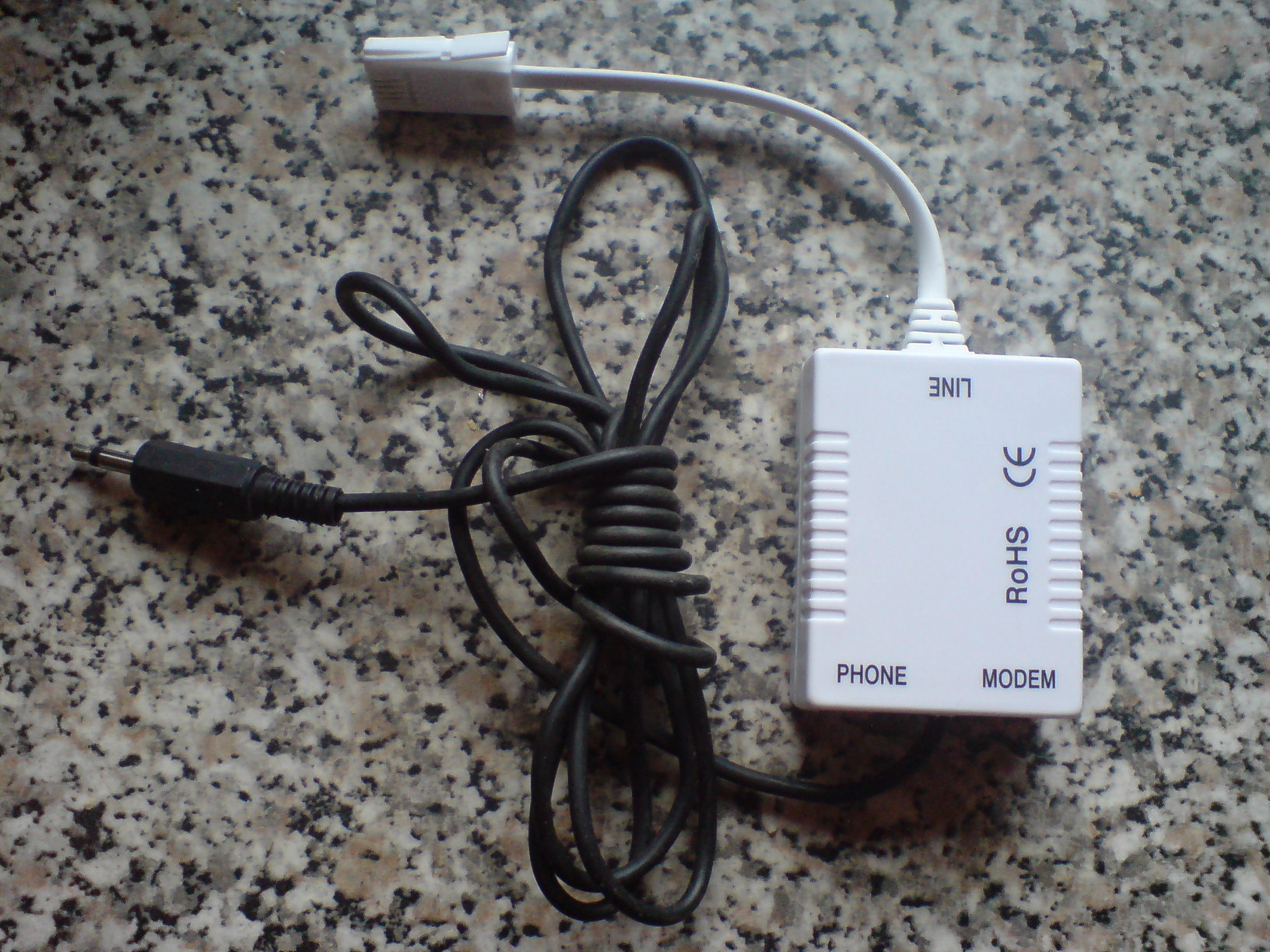
23). Parts you will need to do this simple modification are one ADSL filter box go for the squire version as it has more room in side, Now with a screw driver carefully open the case this should come apart easy as it is just clips on the side.
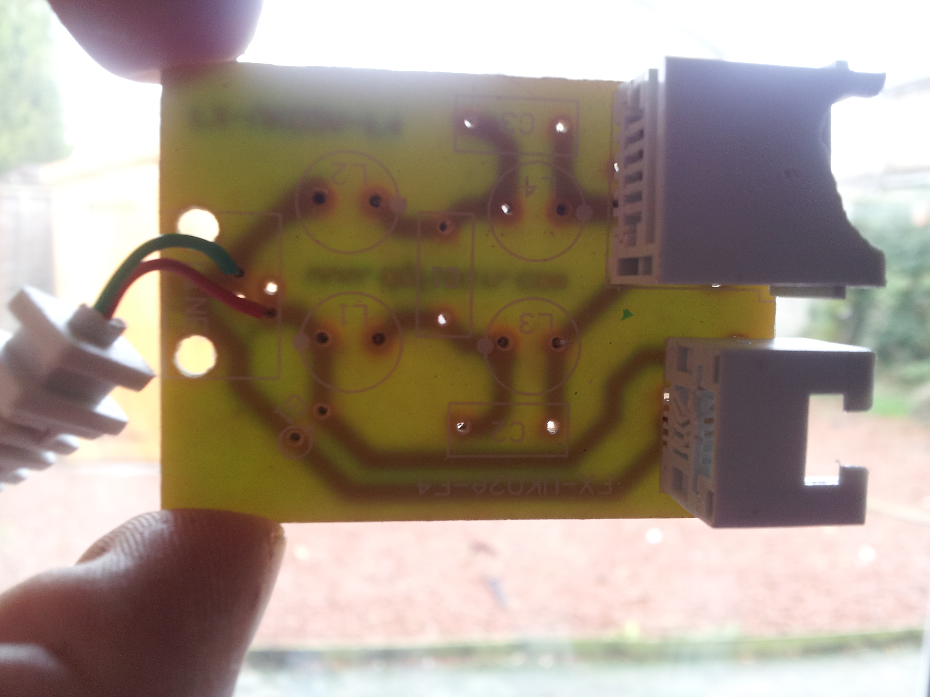
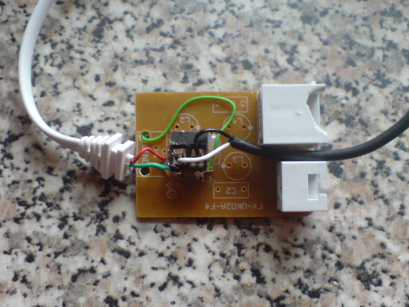
24). Now as you can see the filter circuit board inside we don't need the electronics here so unsolder the coils and the Capacitors out of circuit.
25). Now as you can see from the photo below I have taken out the filters components we have a red wire and a green wire see photo below going to the small connecter
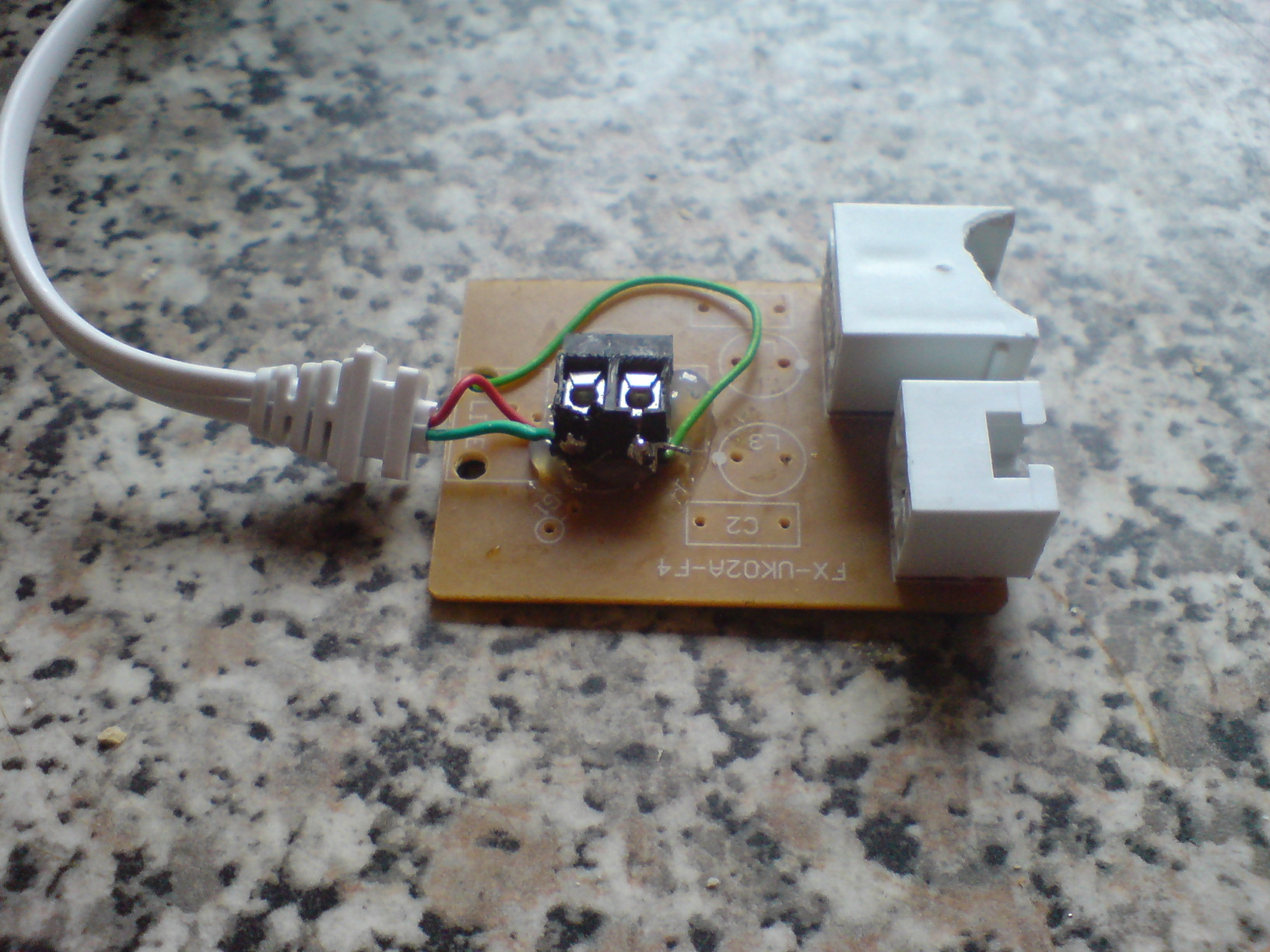
26). Now as you can see from the photo below I have added a small connecter terminal block and soldered the green phone wire to one pin on the block and soldered a second Green wire to the second pin on the terminal block.
27). Now as you can see from the above photo I have a green wire going under the circuit board this is soldered to the same track that the first green wire was soldered to see photo below.
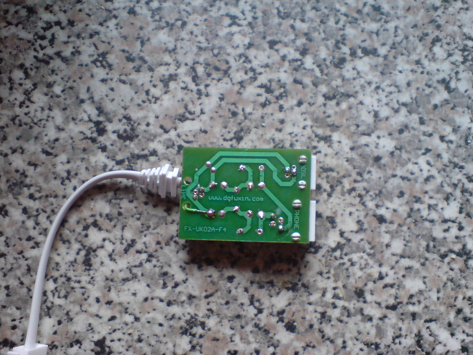
28). Now as you can see where I had the green wire coming from the main phone line to the circuit board I soldered a second wire to the same track now there is a cut in the green wires track by using the terminal block.
In the photo below I have wired up the second phone socket on the board like the first just used jumpers in case you want to use a different phone cable.
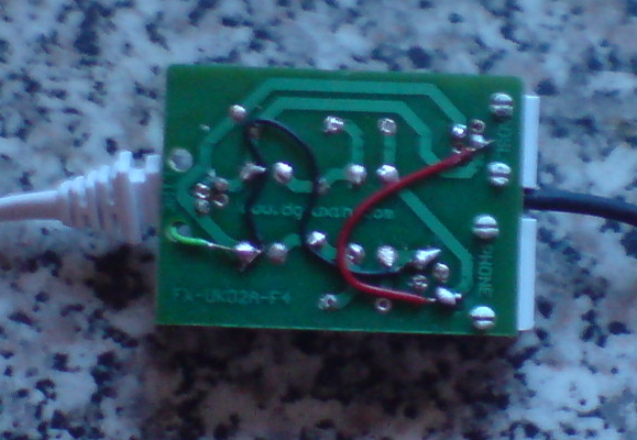
29). Now in the photo below you can see I have added two wires to the connection block with a black cable, Now the end of the Black cable has a PL plug on it you don't need this plug just connect the two wires to the out put of the first DTMF Relay.
In the photo below you can see how to wire up the switch
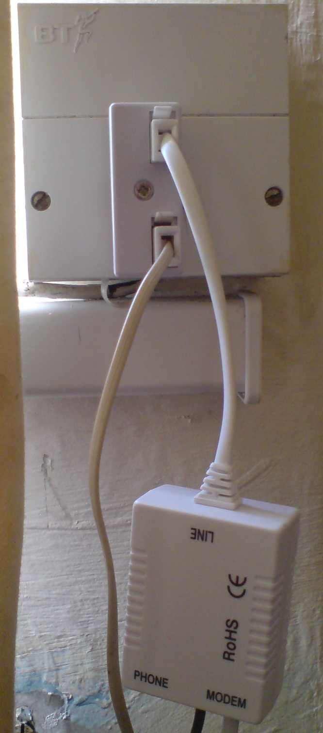
30). Now if you are wanting your cable to come out the middle of the box you will have to cut a little plastic away from the front of the box.
31). Now connect the end of the cable to the back of the relay and plug in your Second DTMF Land line Decoder and cable to the filter box that you have just modified.
32). Now as I used a single channel DTMF remote control all I need to do is phone my mobile wait till it auto answers the incoming call about 4 rings then press * on the key pad and this will turn the relay on and bridge the circuit so my Second DTMF Decoder is now connected to the phone line.
33). Now all I have to do is disconnect my mobile signal and call my Land line phone number and wait for the bleeps then enter my 4 digit security code then enter my commands, When finished disconnect from my land line phone call back the mobile DTMF then press # then the relay will switch off and the Second DTMF Decoder is now switched out of the phone Line.
Here is how to connect a double adapter to your phone line with the Modified ADSL Filter box switch in line with your phone Line.
Please note if you have any problem's Please do E-Mail me I will be more than happy to help: Anthony@anthony-dacko.net