Welcome to this page on how to build your own Passive infrared Detector with a GSM transmitter.
PLEASE NOTE I HAVE DONE TWO SCHEMATIC DIAGRAMS FOR THIS PROJECT BELOW.
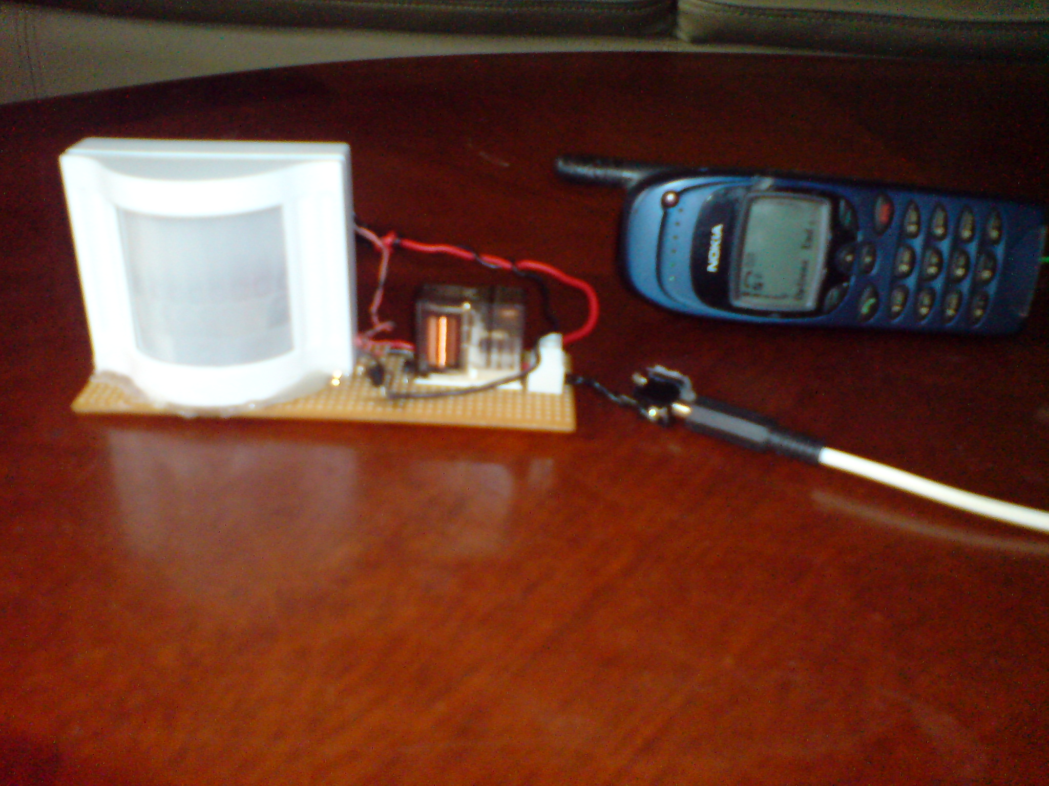
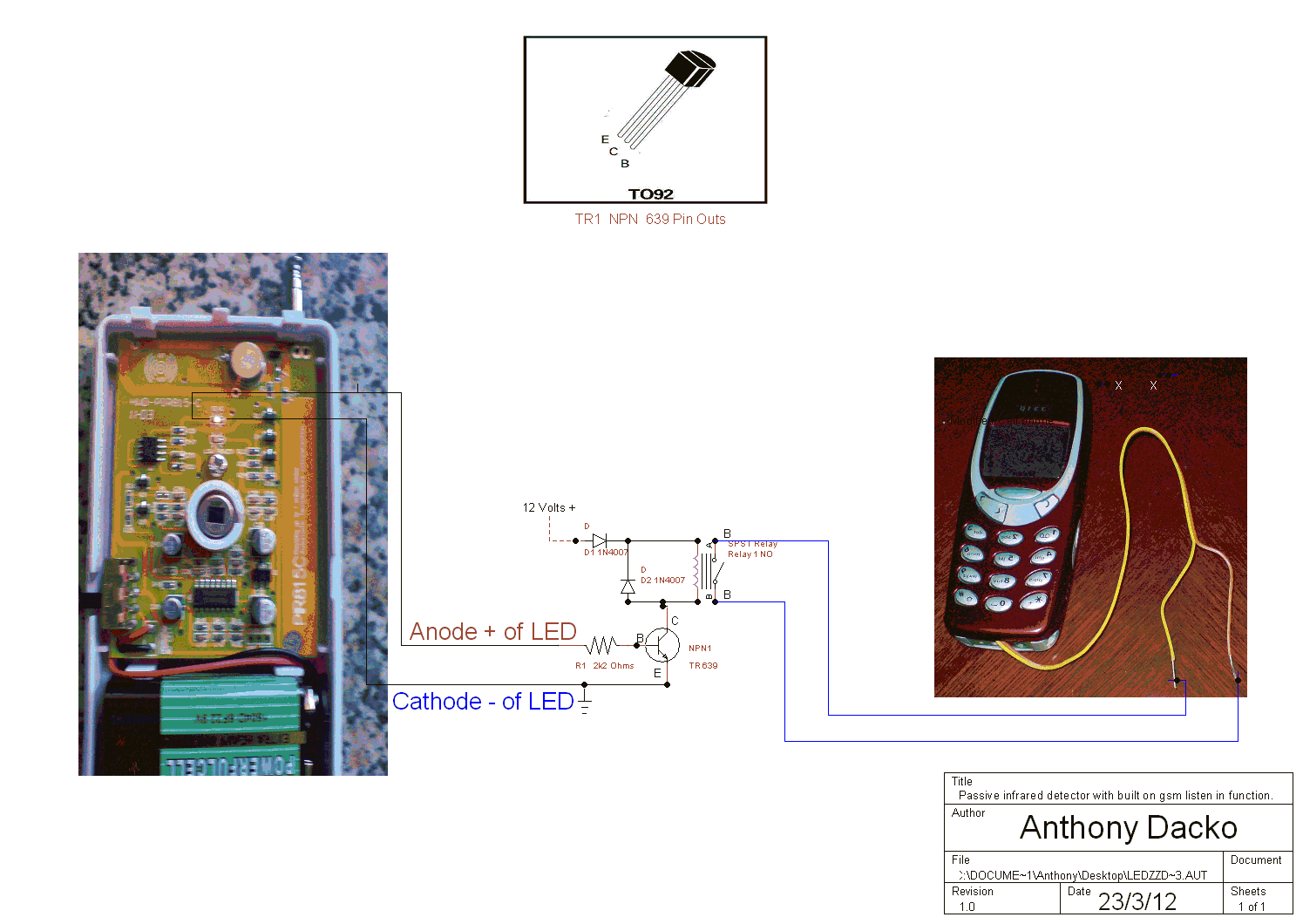
In the photo below is the schematic diagram of how to build your own devise the devise works by taking some of the power from the LED and activating a low voltage switch circuit.
The design will work with any infrared detector as long as the LED stays on for 2 or more seconds to activate the one touch/speed dial of the modified cell phone.
When you come to connect your circuit up to the LED use a test meter to test for the right polarity for the wires Anode is + and the Cathode is -
I designed this simple project to allow me to use a stand alone passive infrared detector that has a LED built in to it to activate a relay when the passive infrared detects some thing it switches on the LED.
The design is useful as it not only detects intruders it also telephones you using the speed dial on the vast majority of mobile phones on the market the devise will not work with touch screen phones.
A quick run down how it works starting with the LED inside a Infrared Detector when the infrared detector detects some thing it will switch on the led.
Now what is happening is some of the LEDs power will flow in to the 2k2 resister and out again this will turn on the transistor this will allow the current in the relay coil to flow to the collector of the transistor and out of the transistors emitter to ground making a loop.
When the infrared is in stand by mode there is no LED on so the current to turn on the transistors base is zero so the current in the relay coil can not flow so the relay stays turned off.
Now looking at the power supply it is 12 volts the first diode is a rectifier 1N4007 this is here to protect the devise from reverse polarity or connecting the wires the wrong way around.
The second rectifier diode is connected to the relay coil this is to stop any EMF this is electro magnetic fields damaging the transistor with a reverse polarity as the relay switches on & off.
How to modify any one touch/speed dial cell phone below.
Now you have all the things you need to modify your cell phone first we will need to load the mobile number in to the phone make sure you have the ringer set to silent all so one touch answer turned off and one touch dial or speed dial turned on.
It would be best to send the signal to a back-up mobile phone when activated as they have caller display on them.
Now say if you put your own mobile phone number into number 5 and connected the wire's coming from the relay to number five this number locked into the phone will be called as soon as the relay closes within 2 or 3 Seconds.
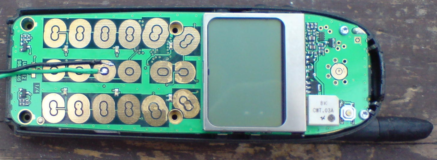
Now I will open my own cell phone after you have opened yours and taken out the screws you may see some thing like this as you can see from the photo below all phones have copper pads this is where we will solder our two wires from the relay if you have loaded your own mobile number in all from 2 to 9 then any one pads will allow you two connect the wire from number 2,3,4,5,6,7,8,9 pads.
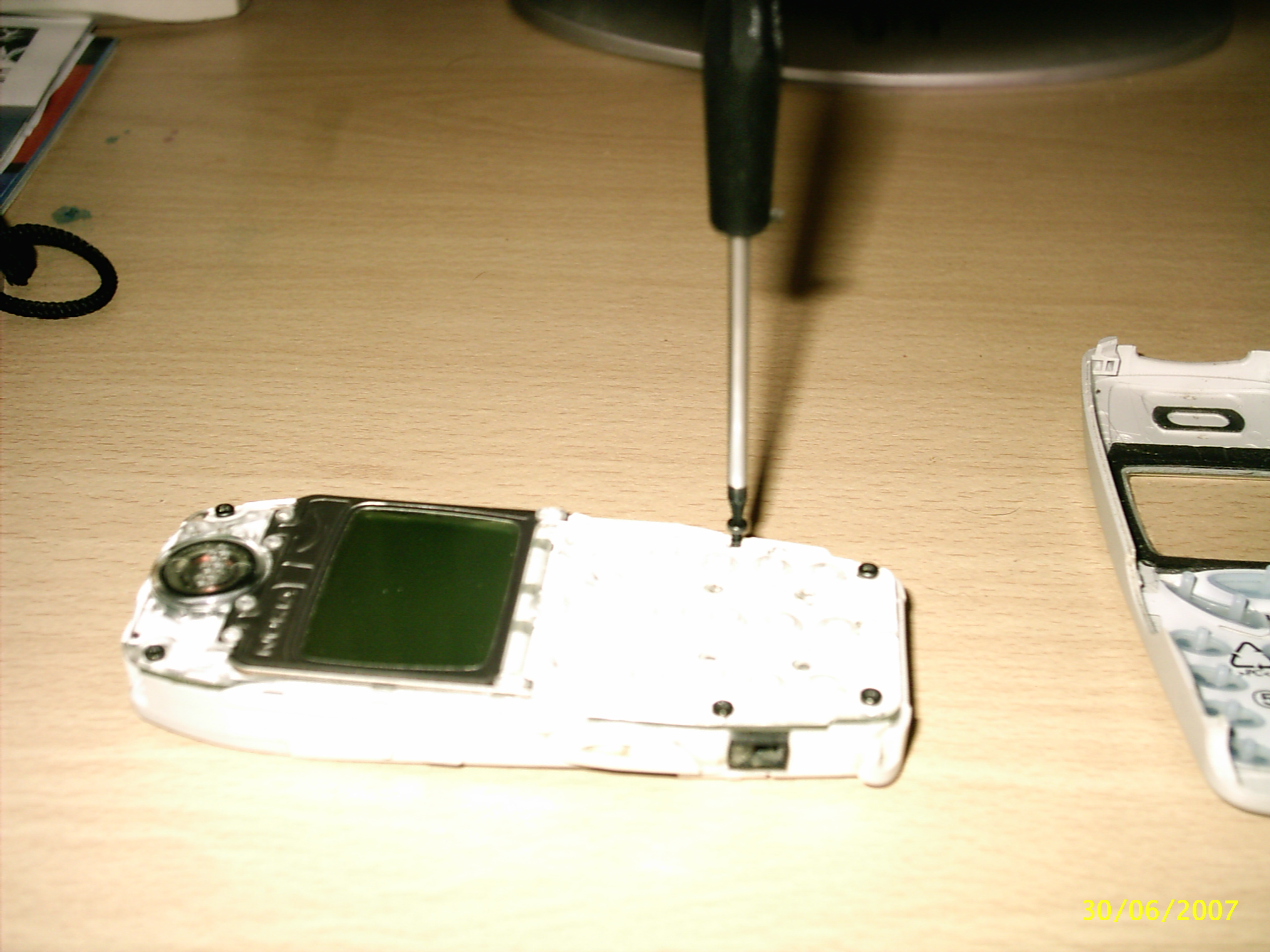
In the photo above you can see the phone with case off
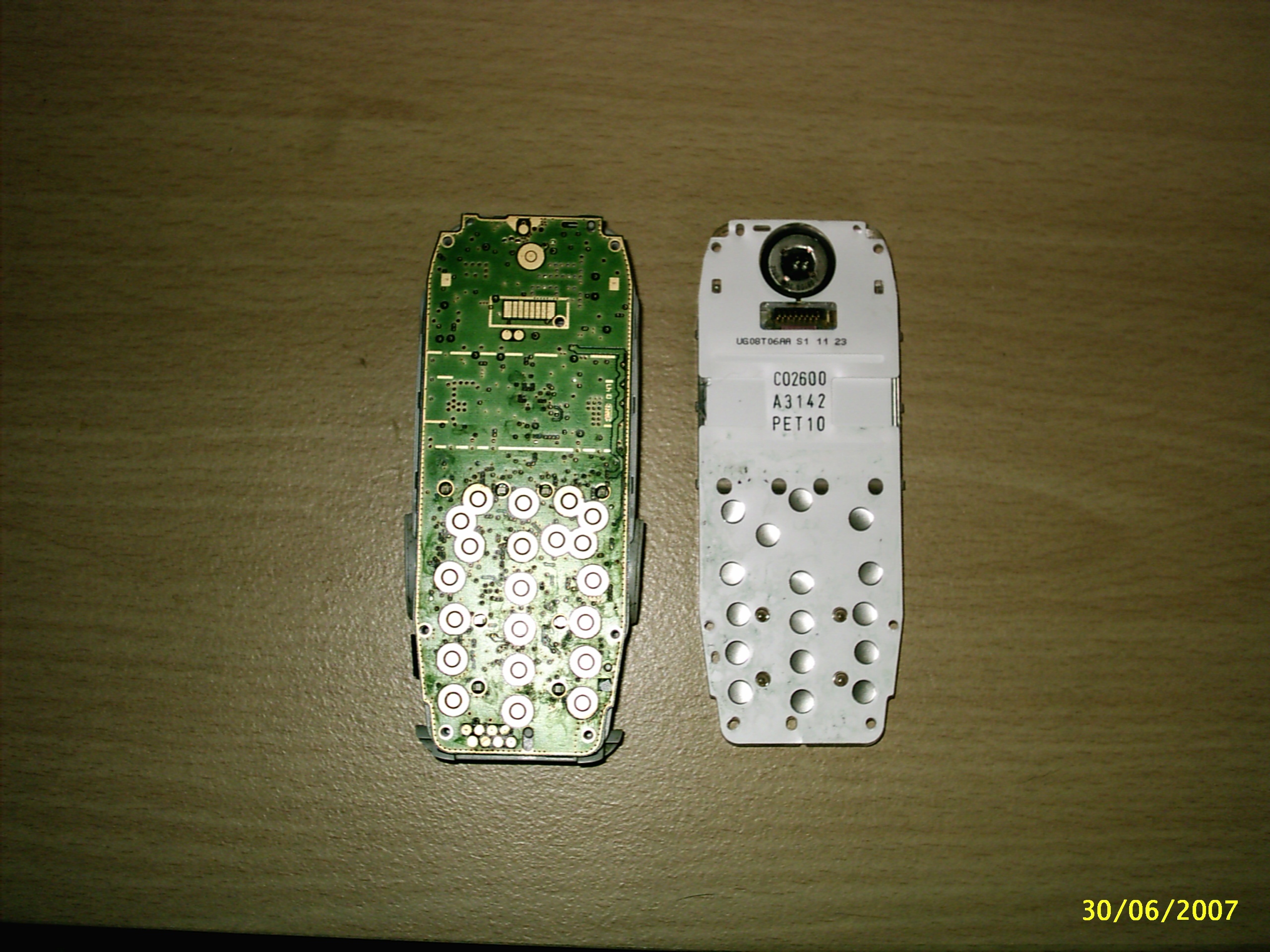
In the photo above you can see how the phone buttons work the white plastic card is covered with silver buttons this is carbon and is what makes the connection to the pads to put the numbers on your screen we don't need this now.
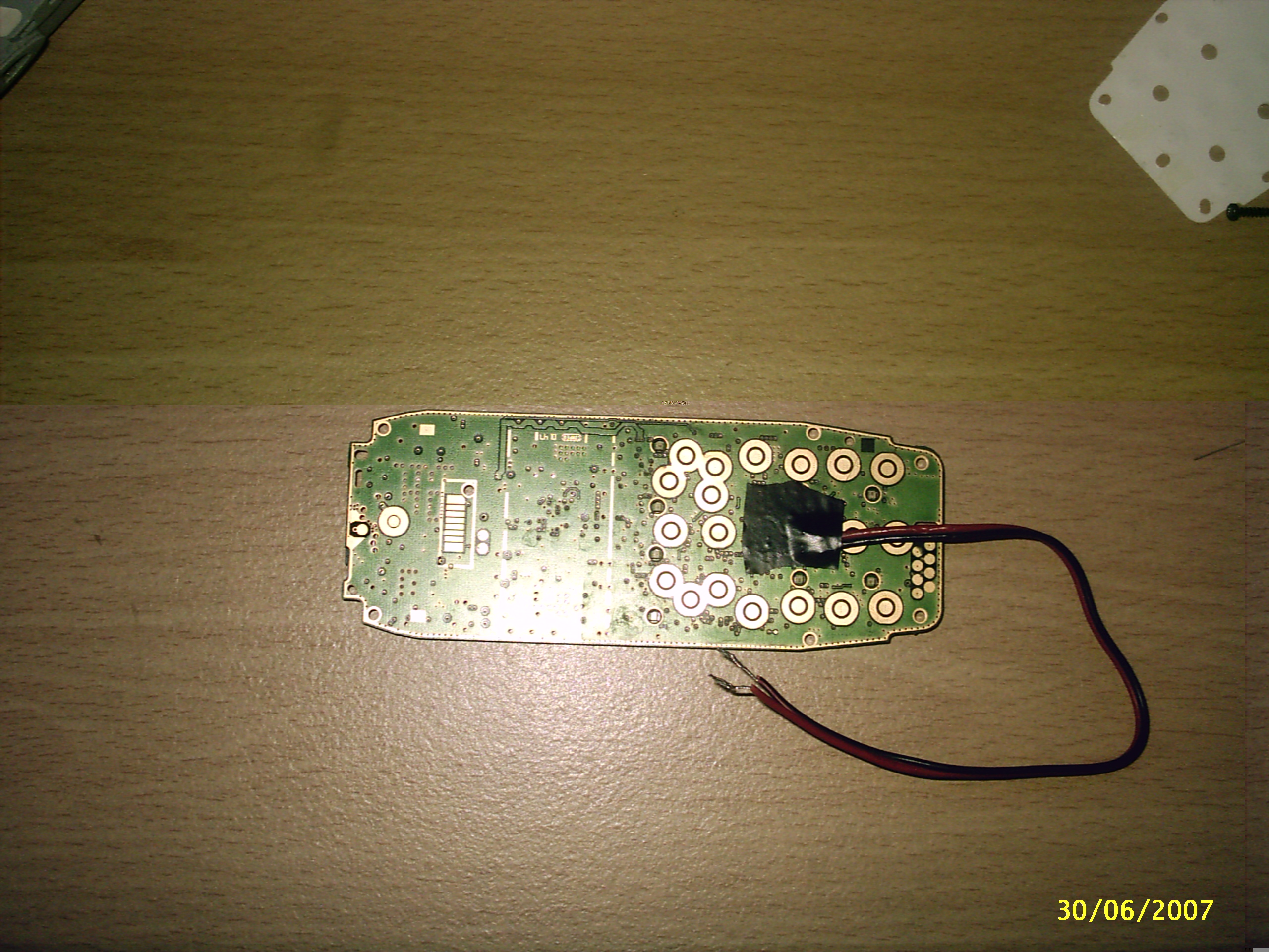
6). Now you will need to tin the two wires before you solder them to the circuit board to do this take off the cover from the wires and very carefully solder the two wires this is called tinning we do this so it is much easer to put the two wires on to the pads.
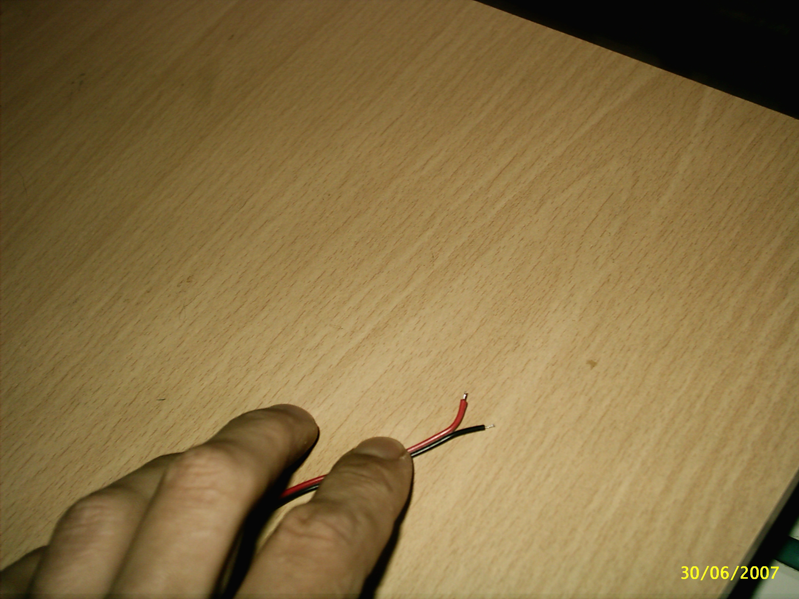
The wire in the photo above has been tined and cut short as I used wire with red and black there is no need to do this speaker wire will work fine.
7). Now look at the pads you have an inside pad and outside pad solder one wire to the inside pad be careful the inside pad does not touch the out side pad and VS or you will get a short or bridge and you will need to use cleaning tools to try and fix it. .
8). Now when you come to fix your wires to the pad put one wire in side the pad and using your soldering Iron push down on the wire this will heat the solder so it fixes to the pad do the same with the next bit of wire but connect this to the outside pad.
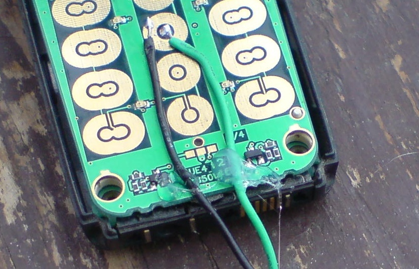
In the photo above you can see I have soldered the two wires to the in & out side pads of the modified phone in the photo above I used my Nokia phone as this was a better photo than the one I used before.
You may also want to add a little bit of hot melt glue to the bottom of the wires to take some of the stress from the solder contacts see photo below.
Any phone with touch button and one touch dial/speed dial will work.
9). Now you will need to add some PVC tape over the pads like in the photo below.
In the photo below is the Schematic diagram keep in mind the simple circuit needs to have the LED on for 2 or more Seconds to make the call to you to let you know it has been activated.
I Designed the schematic below to allow the Passive infrared to keep sending out a call signal every time the passive infrared detector detected the intruder passing the infrared signals, This is useful if you did not hear the call the first time.
You may want to send the signal to a back up Cell phone you carry with the Answer phone turned off so it does not go to the answer phone.
Please note both designs will allow you to listen in to the back ground sound if you answer the income call.
Now if you don't want to get charges for the call set on your phones screen GSM activated then just disconnect the incoming call as this allows you to see on your phones screen that some thing has activated your Passive infrared detector.
Now in the schematic below I have used my first design but modified it with a Latching Relay to latch the relay on till turned off manually.
The 12 Volt Latching relay can be
got from bits box Latching Relay DPDT
twin coils - set and reset. Operating voltage 5V or 12Vdc available 2A 30Vdc 1A
125Vac contact rating.
Pins arranged on a 0.1" grid. Click
here.
Now in the Schematic below I have designed this Latching Circuit with a SCR
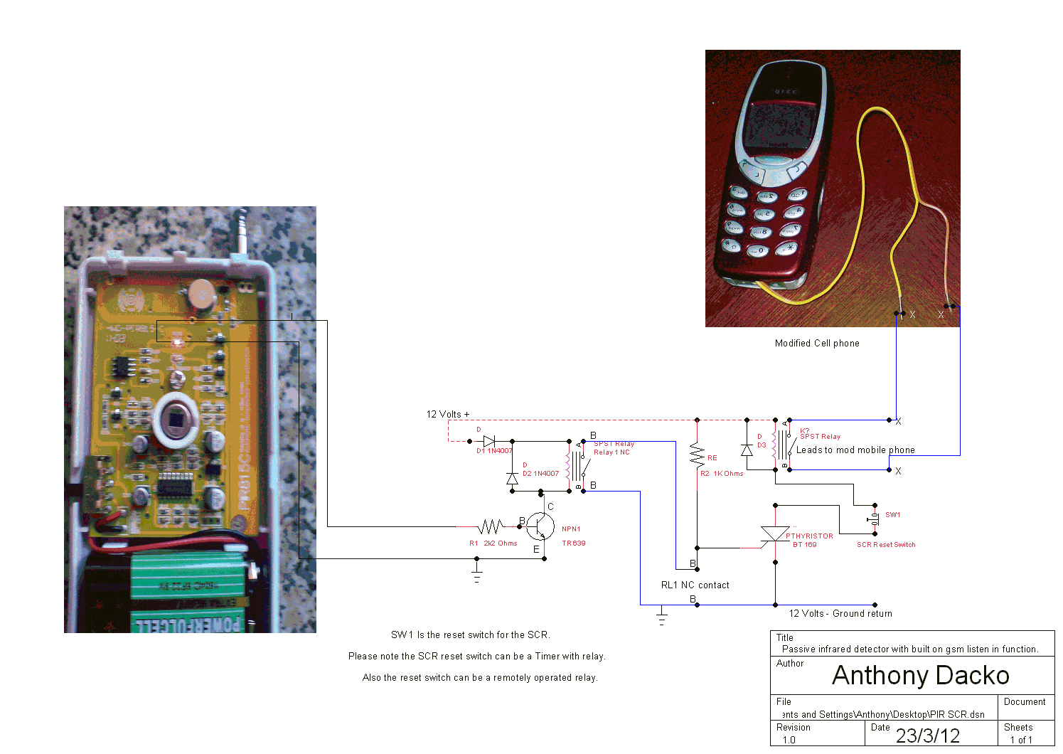
Now as I have added more on to my first design this design above will only activate once and latch useful if you use a Passive infrared with a short LED on time also it won't keep phoning you.
Now how the second design works is when the LED is switched off the relay one is off this allows the current flowing in resister R2 to act as a load and send the current to ground.
Now when the LED switched on this will activated the Relay on and turn the Normally NC contacts to a NO this will stop the flow of current to ground using R2 now the Current flowing in to R2 goes to the SCR's Gate and allows the Thyrister to conduct from Anode to Cathode.
Now what happens is that the current in the Relay 2 switches on and activates the modified cell phone. The Diode is there to protect from EMF as soon as the LED switched back off relay 2 will say on you need to cut the power flowing in to the Anode to reset it this can be a switch.
The parts are all off the shelf components so you should have no problem getting the parts for this project from any where.
The 12 Volt Latching relay can be got from bits
box Latching Relay DPDT twin coils - set
and reset. Operating voltage 5V or 12Vdc available 2A 30Vdc 1A 125Vac contact
rating.
Pins arranged on a 0.1" grid. Click
here.