Welcome to this simple page on turning a simple radio link for a few hundred feet into being able to turn on the Transmitter from any where in the world.
(Part Two Setting every thing up)
Please note you don't need any expensive test equipment like in the photo above this is my own equipment.
1). Now if you have got the light switch in kit form then build it first to keep this as simple as possible we will keep the soldering to a minimum or not at all.
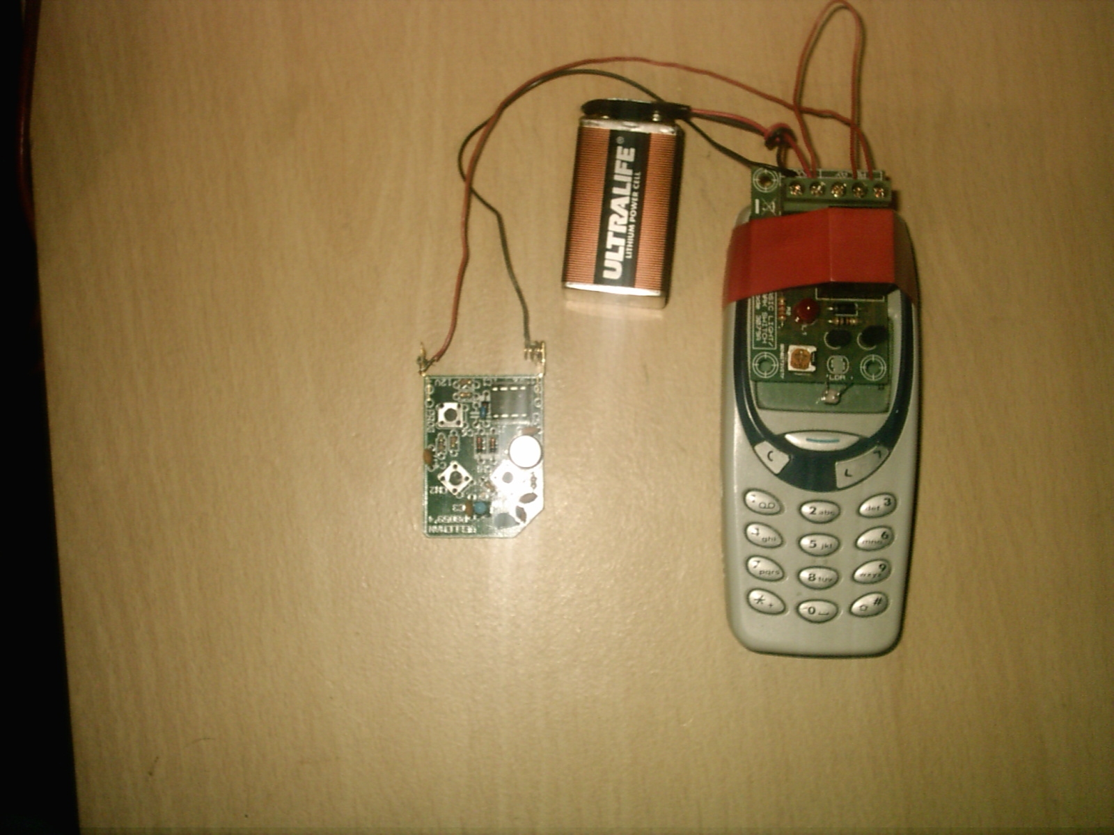
2). Now put your light kit on top of your phone like in the photo below and connect the PP3 Battery clip and Battery also put some PVC tape around the relay to hold the kit onto your mobile phone.
3). Now connect the red wire to the + V of the kit and the black wire to the - V of the kit see photo below remember to take some of the covering off the wires first.
In the photo above I am holding down the LDR Component to stop the kit turning on.
4). On the kit you will see a yellow dial go to a dark place and push on one of the buttons on the mobile phone if the kit turns on and the Red Led light comes on and you hear a click from the relay then this is working fine.
If the LED light did not turn on then turn the dial till it does come on and you should all so hear a click from the relay as it switches over this is the first part of the kit working fine.
5). Now we will add two wires from the back of the kit connect one wire to the screw down terminal marked NO and one wire to the Screw down terminal C see photo below.
Now that you have attached the two wires to the NO & C Connecters.
6). When you have connected the two wires from the NO & C terminals the wire coming from the C terminal connect this to the red wire of your battery clip and twist them together now connect a second black wire to the black wire on your Battery clip and do the same as before.
7). Now connect the red wire from your Battery clip to the + V terminal and connect the black wire to the -V terminal see photo below.
Please note the NC terminal is not used here.
8). Now if you have a test meter connect the black long wire to the black test probe and the red long wire to the red test probe connect your battery.
9). Now if your L.E.D. light is on then you should be reading the volts from the battery this wants to be within 8 or more volts see photo below.
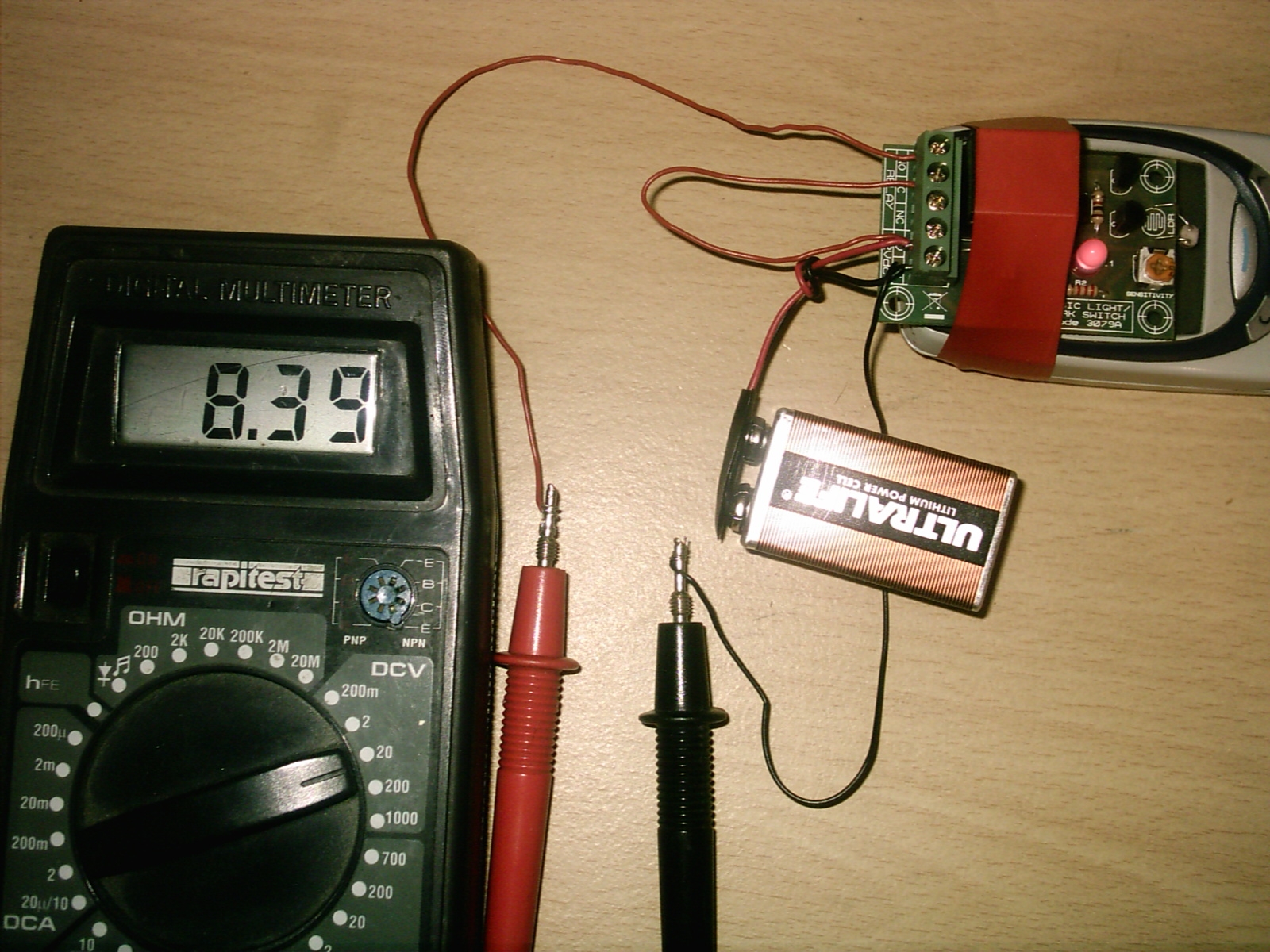
Now as you can see from the test meter it is reading just over 8 volts this is fine all so see the red L.E.D light is one.
10). Now you may be thinking why is the L.E.D light on this is down to the back ground light this is why we need to put the devise in a dark place.
Why we are reading the volts from the unit is simple this is what will power our mini transmitter if you phone the mobile with the kit on it the light from the phones own screen will switch the relay over and power your mini transmitter.
11). Now in the photo below you can see how to connect the two long wires to your mini transmitter connect the black wire to the spring and the red wire to the next connecter if you have a soldering iron then solder the wires to the transmitters battery terminals if not just put tape around them.
The photo above is of the near finished unit what we need now is some thing to hold down the button so when the power goes to the unit it will transmit a signal to the receiver.
12). Now I would recommend you solder a small wire at the bottom of the button but as I want to keep this as simple as possible I will just put a very small stone on the Button and add tape to hold it down see photos below.
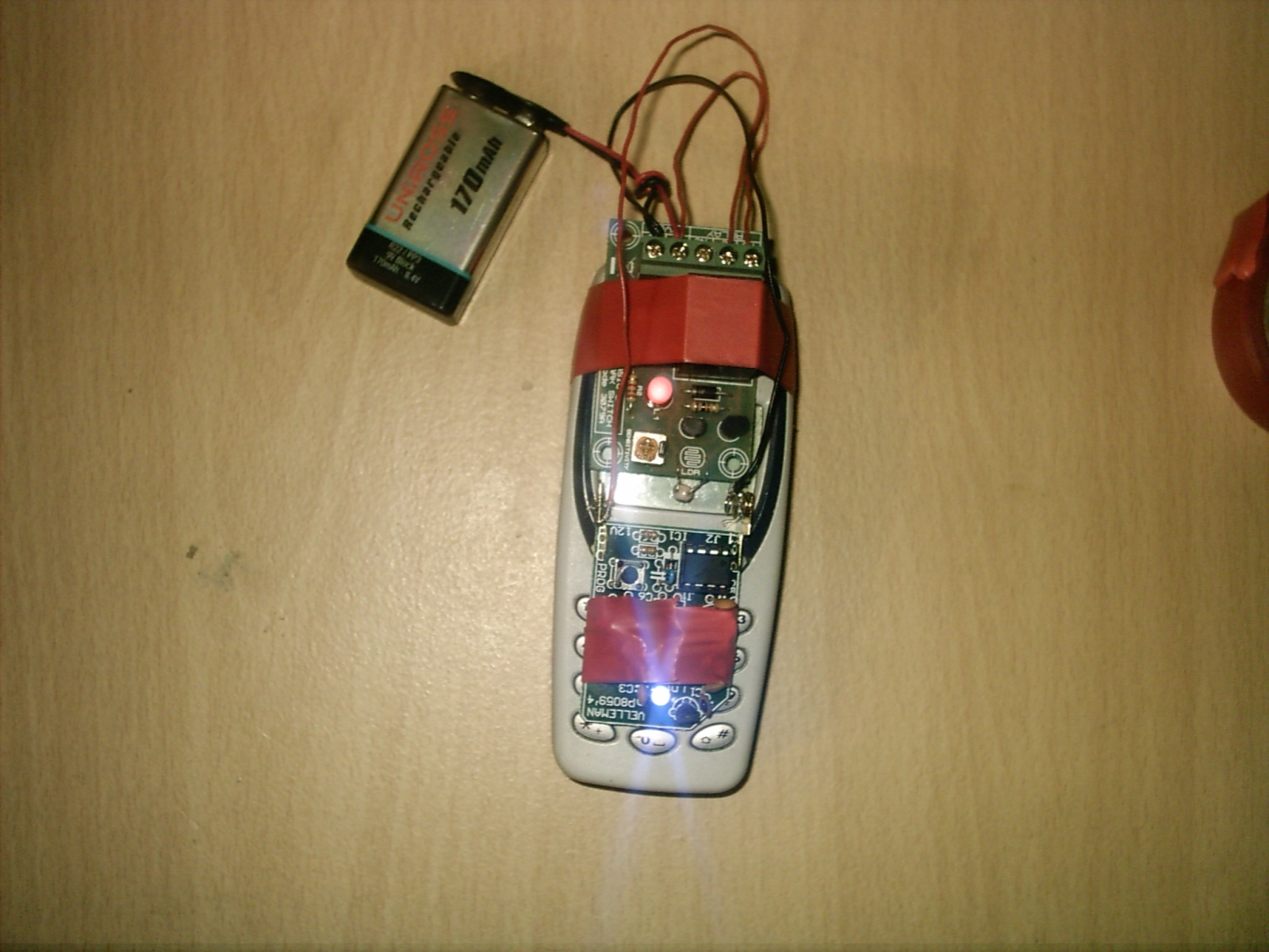
Now as you can see from the finished unit the light on the transmitter is on this is sending a signal to the receiver.
13). How the unit works is simple when you telephone the mobile phone light from the phones screen lights up and the LDR allows electrical current to flow turning on the relay and sending power to the transmitter you can be any where in the world and activate the transmitter by Cell phone or Lind line.
14). When the phone light turns off the power to the transmitter will also be cut off as well ready for the next call to turn it on or send a second signal to turn the receiver item connected to it off.
15). You may have a timer set on your receiver that will switch off after a given time again depending on your set up you can have any electrical item connected to the receiver channels 1 or 2.
Please keep within the Law have fun and don't forget the unit must be put in a dark place.