Welcome to this very simple GSM doorbell design, I designed this for
deaf people or hard of hearing but any one can use the design if they don't
want to miss a push of the doorbell like postmen or couriers or friends at your
door again.
Now
if you would like to see the video of this working then visit my You Tube page
here
The benefits of my design are unlimited range, No need for a internet
connection or Wi- Fi connection, No need to use a Smart phone as it can work
with a cheap mobile as well you can use a smart phone if you like see video.
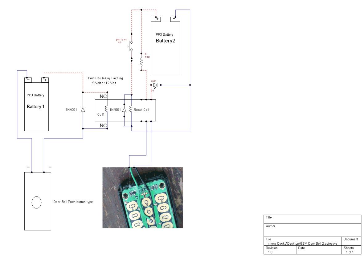
In the Schematic diagram below I have added a Super
bright White LED in to the design so when the doorbell is pressed it will turn
on the LED.
Resister 1K Ohms
LED Super bright White one.
Relay 12 volt
1). Why I designed
this GSM door bell schematics is mostly for deaf people or them that are hard
of hearing, The design is very simple and cheap to build all the parts are off
the shelf components.
2). There are a
number of deaf aids for people with hearing loss the only problem most are just
loud sounds when some one presses on the door bell or flashing lights come on
when the door bell is pressed.
3). In this design
I have used a modified cell phone to call a second mobile phone with Vibration
turned on this is a better idea than just a loud sound as it can do much more
if the person has the phone in there pocket it will vibrate to let them know
some one is at there door.
4). The nice thing
about this design is on the owners mobile they can put the door bells mobile
number in there mobile and put the name in for the incoming call as door bell or Door Bell Ringing.
5). Now how the
simple door bell works is like this as soon as some one presses the door bell
this will allow current flow in to the door bell and out again making the
connection to the pads on the mobile just like you pressed the number key your
self to make the Call. Now we will look at a Latching relay coil and as it is a
Latching relay it will be held magnetically even when the person releases the
push button.
6). Now as the
rely latches this will hold the relay in position and activate the one touch
dial on the cell phone just like you pressed the key on the phone your self.
7). Now all you
have to do is with the second switch push on it this will reset the first coil
back to normal and ready for the next door bell press again.
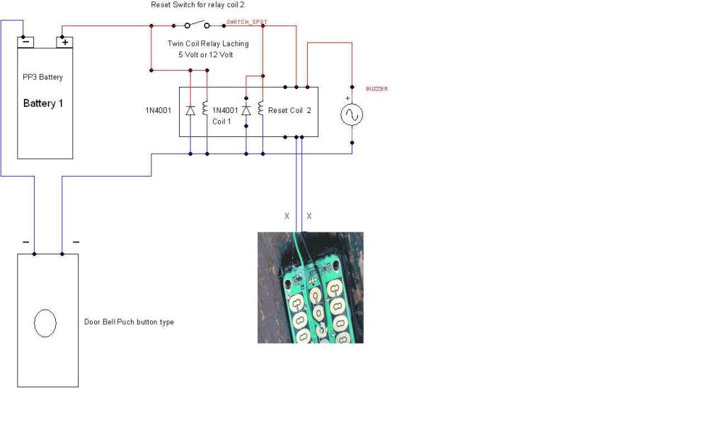
In the Schematic below I have added the
reset switch to the same battery as the first relay as there is just a second
to set the coils in position after the door bell is pressed only a second of
power is used in this design.
Connect the two wires( x x) Coming from the relay to the to wires
coming from the mod cell phone.
In the Schematic below I have added
a buzzer as well.
In the Schematic diagram below I
have used my same design but added a second battery to the design this is to
add a LED so its not being powered from the first battery, When the Door bell
is pressed it turns on the LED also and this stays on giving you visual indication
your door bell was pressed just use the reset switch to reset the coils back to
normal.
Now how to do the Modification to the cell phone so it can used
the activate the one touch/Speed dial when the doorbell is pressed.
8). Now you have
all the things you need to modify your cell phone first we will need to load
the mobile number in to the phone make sure you have the ringer set to silent
all so one touch answer
turned off and one touch dial or speed dial turned on.
9). It would be
best to send the signal to a mobile phone when activated as they have caller
display on them now how this works is when the bell is activated it will turn
on the relay and phone the number locked in the Sim card.
10). Now say if
you put your own mobile phone number in number 5 and connected the wire coming
from the relay or in this case to number five on the circuit board then this
will call your mobile phone.
11). I know most
Sim cards will work fine around the world if you can program different numbers
into your phone say from 2 to 9 and have speed dialling or one touch dialling
set then this will work fine for you .
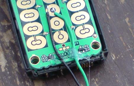
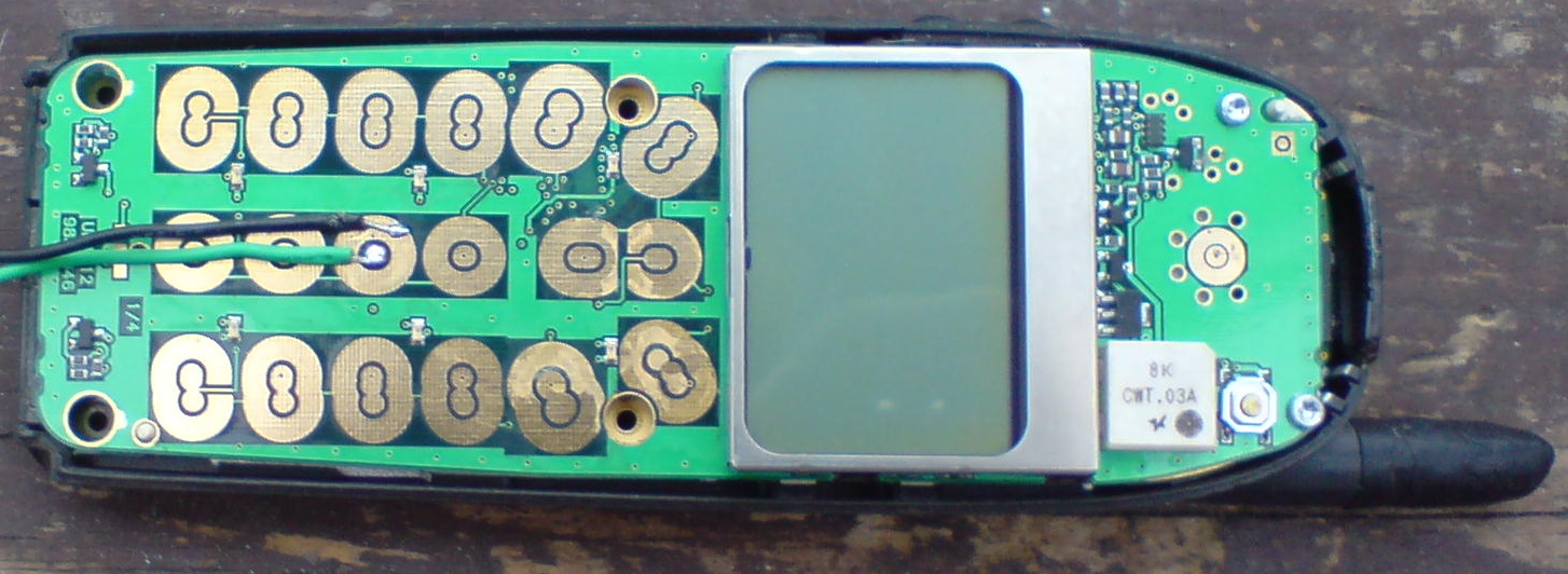
12). Now I will
open my own cell phone after you have opened yours and taken out the screws you
may see some thing like this as you can see from the photo below all phones
have copper pads this is where we will solder our two wires from the relay if
you have loaded your own mobile number in all from 2 to 9 then any one pads
will allow you two connect the wire from number 2,3,4,5,6,7,8,9 pads.
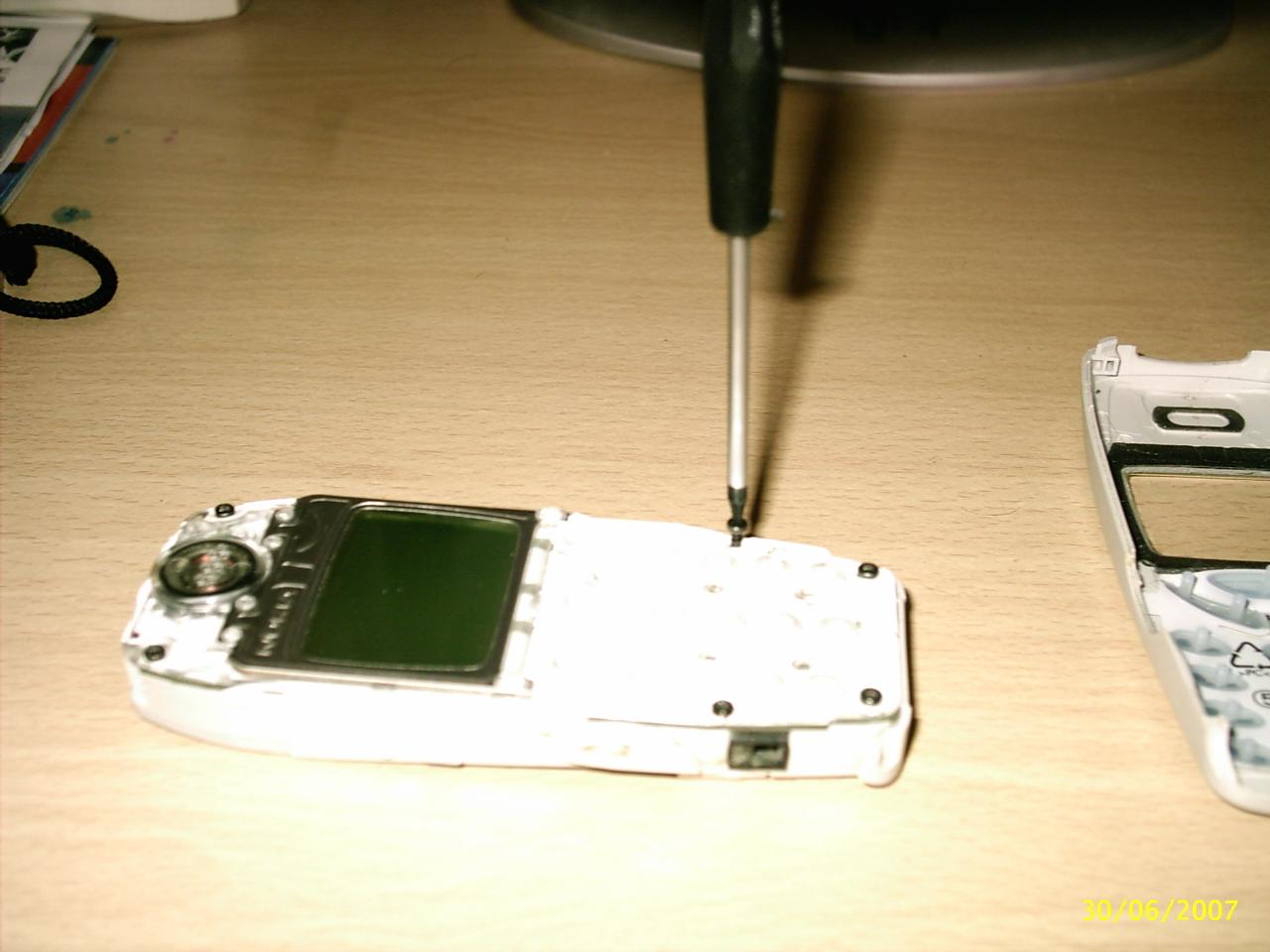
In the photo above you can see the phone with case off
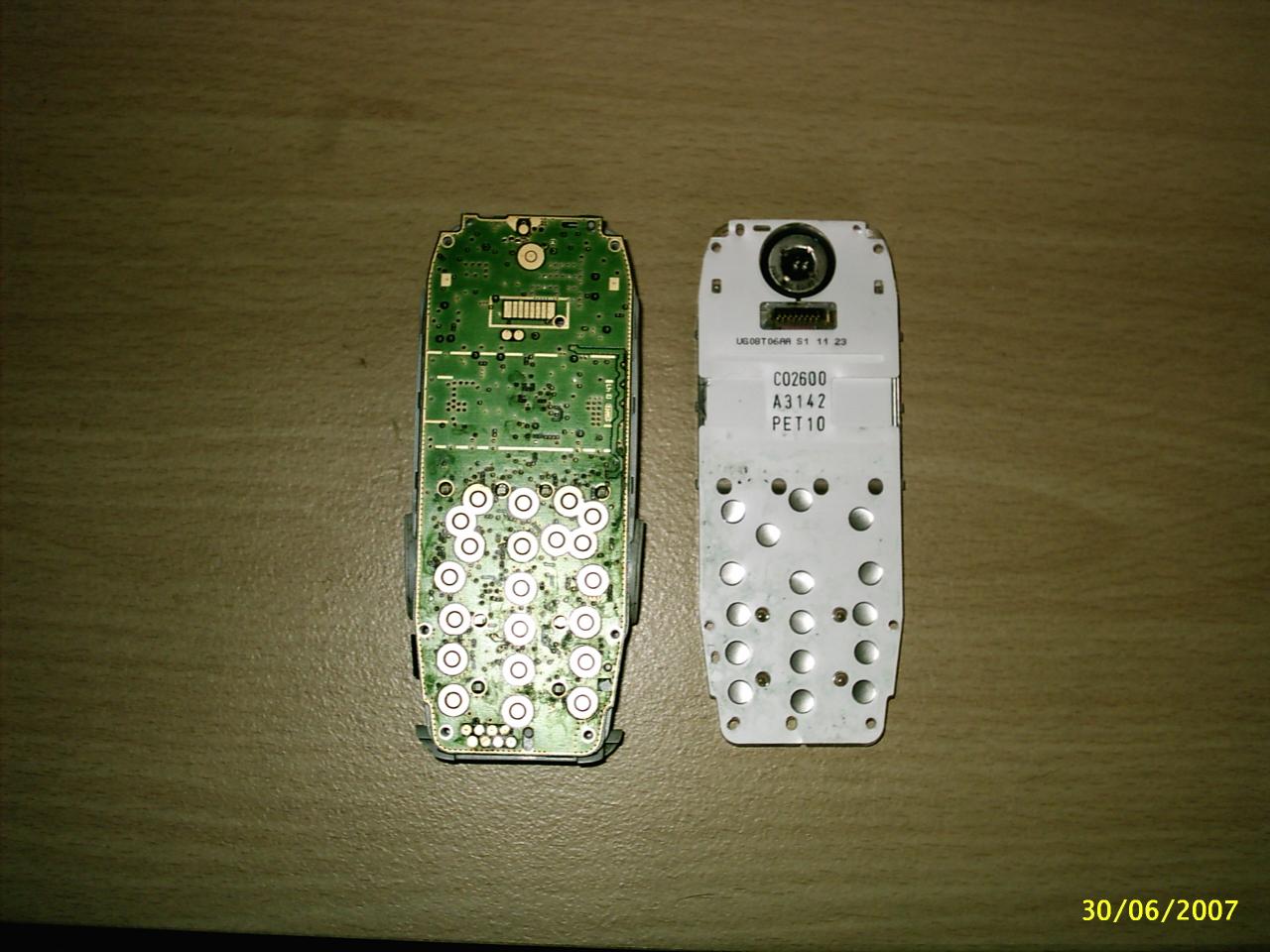
In the photo above you can see how the phone buttons work the
white plastic card is covered with silver buttons this is carbon and is what
makes the connection to the pads to put the numbers on your screen we don't
need this now.
). Now you will
need to tin the two wires before you solder them to the circuit board to do
this take off the cover from the wires and very carefully solder the two wires
this is called tinning we do this so it is much easer to put the two wires on
to the pads.
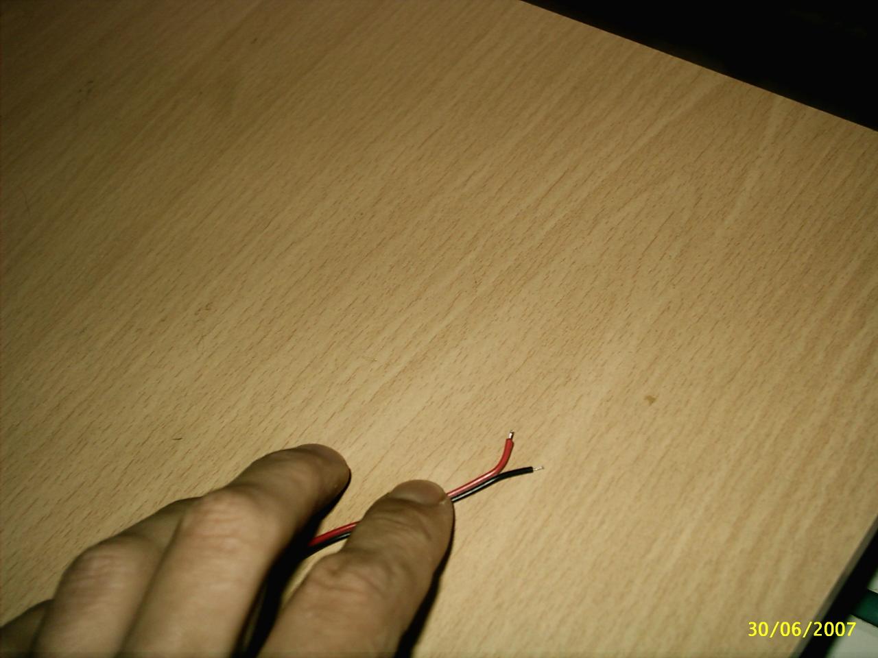
The wire in the photo above has been tined and cut short as I used
wire with red and black there is no need to do this speaker wire will work fine.
13). Now look at
the pads you have an inside pad and outside pad solder one wire to the inside
pad be careful the inside pad does not touch the out side pad and VS or you
will get a short or bridge and you will need to use cleaning tools to try and
fix it. .
14). Now when you
come to fix your wires to the pad put one wire in side the pad and using your
soldering Iron push down on the wire this will heat the solder so it fixes to
the pad do the same with the next bit of wire but connect this to the outside
pad.
In the photo above you can see I have soldered the two wires to
the in & out side pads of the modified phone in the photo above I used my
Nokia phone as this was a better photo than the one I used before.
You may also want to add a little bit of hot melt glue to the
bottom of the wires to take some of the stress from the solder contacts see
photo below.
Any phone with touch button and one touch dial/speed dial will
work.
Now if you need
any help with any thing I have designed than I am more than happy to help drop me
an e-mail: anthony517654@gmail.com
www.anthony-dacko.net/electronic