Welcome to this page on setting every thing up for the Service Dog GSM phone with one touch activation also with sounder now.
Please note the above unit will be equipped with a test button soon also note when you release the test button the unit will work like before.
![]()
If you have not seen the first part of this project then Click here
Now on the following page we will start to build our unit if you do a good job of it then at the end of the project you should have a working unit follow the information below.
I will just follow on from my last version but in this version we will be using a relay to activate the cell phone also a sounder with a on/off switch.
In this design we can turn the sounder on or off if the unit gets activated but it does not matter if the sounder is on or off the cell phone will still dial out to the prefixed number if the unit was activated this is a safety feature of the design I have built in.
12). Now First off you should have modified your cell phone and modified your Peg if not click here. You will all so need to Tin all your wires as well to get a better contact.
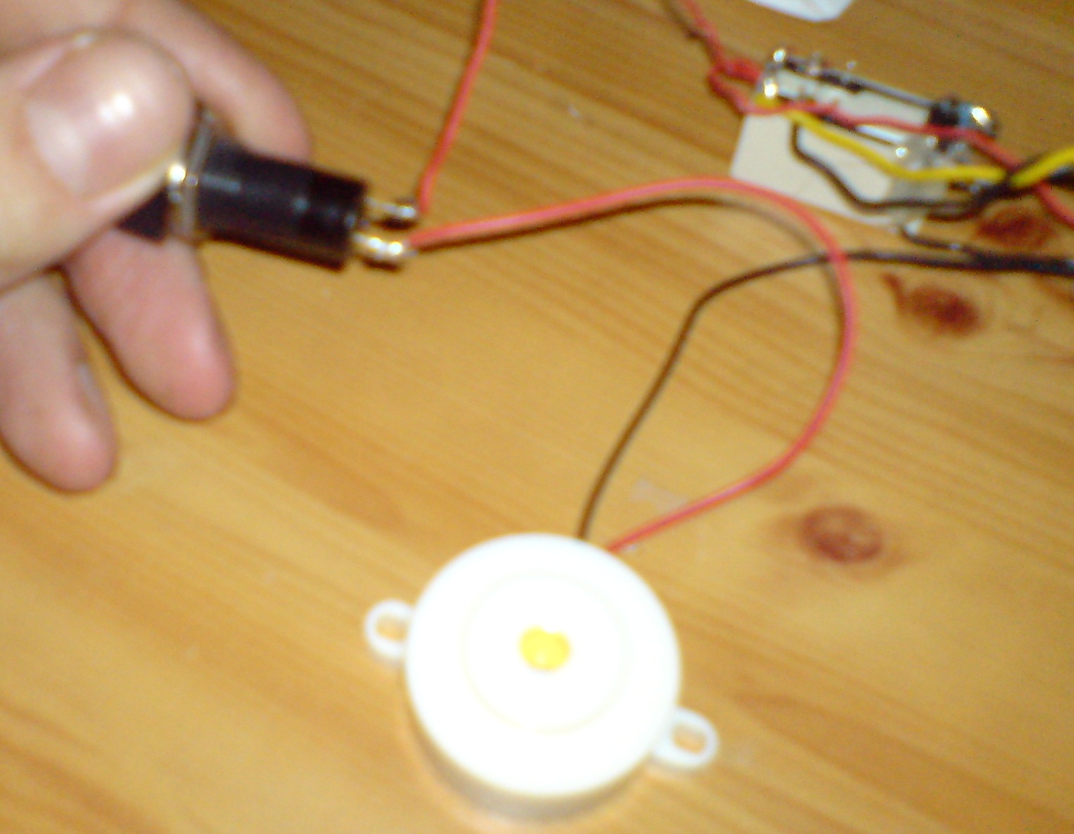
13). In the photo below I have soldered my 1N4003 Rectifier Diode 1A 50V Diode to the first two contacts on my relay see the two long metal pins coming from the front of the relay. Why we need to solder the diode is down to the relay making EMF the diode passes current in one direction only.
14). Now it does not matter which way round you solder the diode as long as it is soldered to the first two pins on the relay.
15). Next I have soldered one wire to the middle pin of the relay and the second wire to the last pin same side on the relay this is our connecter for our cell phone socket.
Testing the unit below before you carry on is a good thing
Now in the photo above you may like to test the relay by plugging your modified cell phone in to the 3.5mm socket that is fixed to the pins on the relay and touch the diode pins with the battery you should hear a Click sound then the phone activating.
18) Now on the opposed side of the relay solder two more wires this will be going to our sounder and on/off switch see photo below.
7). Now solder one of the peg wires to the + side of the diode this is the side away from the Silver band on the diode see the photo below.

8). Now in the photo above we have connected our Diode to the first relay contacts this will be the coil contacts also we have soldered our 3.5mm socket to the middle and back contact pins on the relay.
9).The 3.5mm socket is for the mobile phone plug to plug in to the second two wires on the opposed side of the relay middle and back pins go to our on/off switch for the buzzer/sounder.
10). Now in the photo above you can see I have connected one of the blue wires from the Peg to the Red + lead on the Battery Clip.
11). Now connect the second blue wire from the peg to the + part of the diode this is the part away from the silver band.
12). Now at this point solder a black wire from the - silver band on the relay to and connect this to the black wire in the connecter block see photo above.
13). Now at this point connect your cell phone to the 3.5mm socket and take away the Shim from the silver contacts on the Peg. Now touch the battery to the Clip you should here a Click sound and about 2 or 3 Seconds later the phone should activate the prefixed number.
14). Now in the photo above you can see I have soldered two orange wires to the opposed side of the relay this is for our sounder and on/off switch solder one orange wire to the on/off switch contacts see photo below.
15) Now solder the Buzzers Red wire to the second contact on the on/of switch like in the photo below.
16). Now connect the buzzers Black wire to the connection block see photo below it needs to connect to the same side the black wire from the battery clip is coming in.
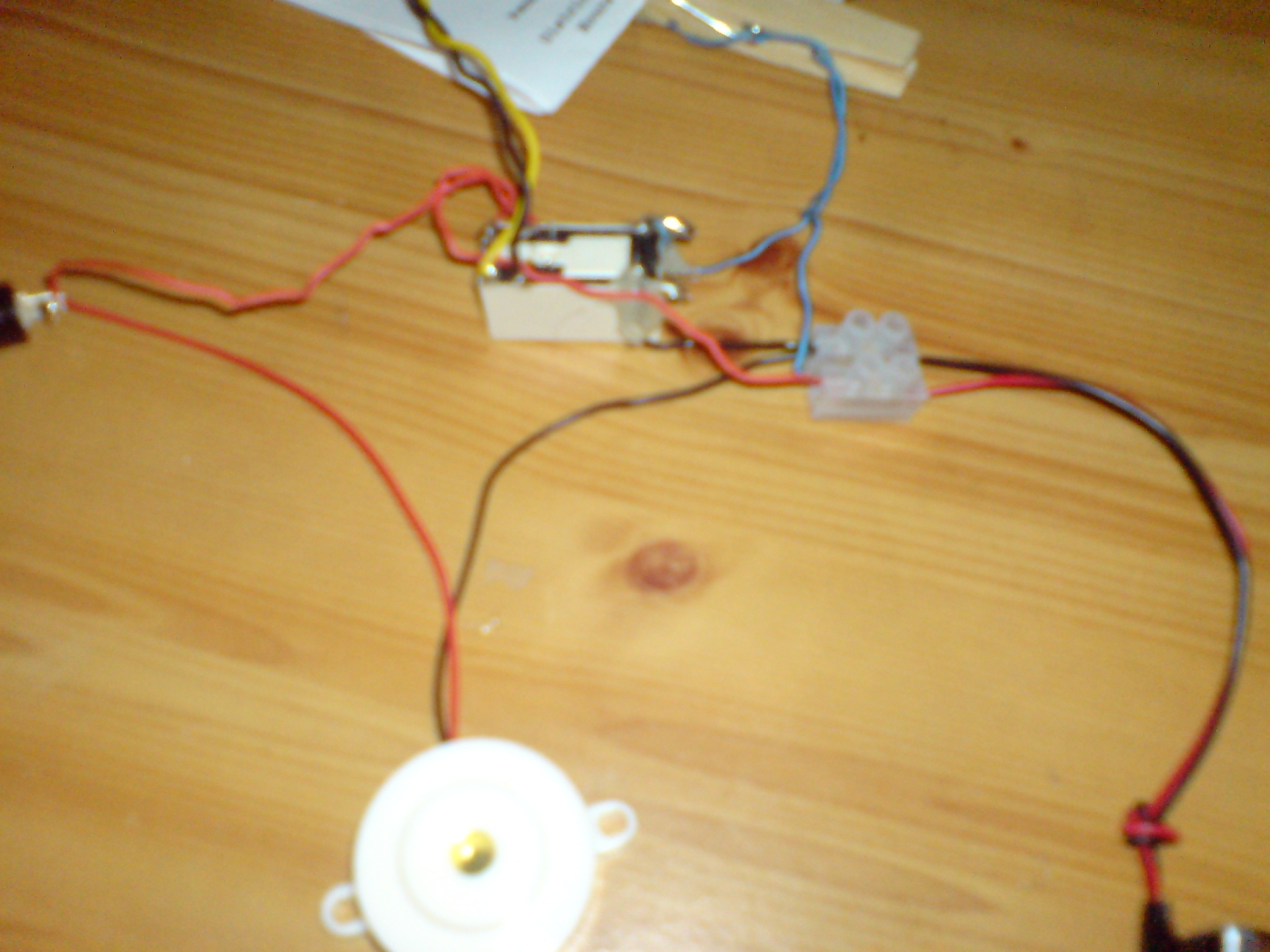
17). Now the second orange wire from the back of the relay needs to connect to the connecter block put this wire in the Red side of the connecter block so the red wire from the battery clip is in the same connecter block.
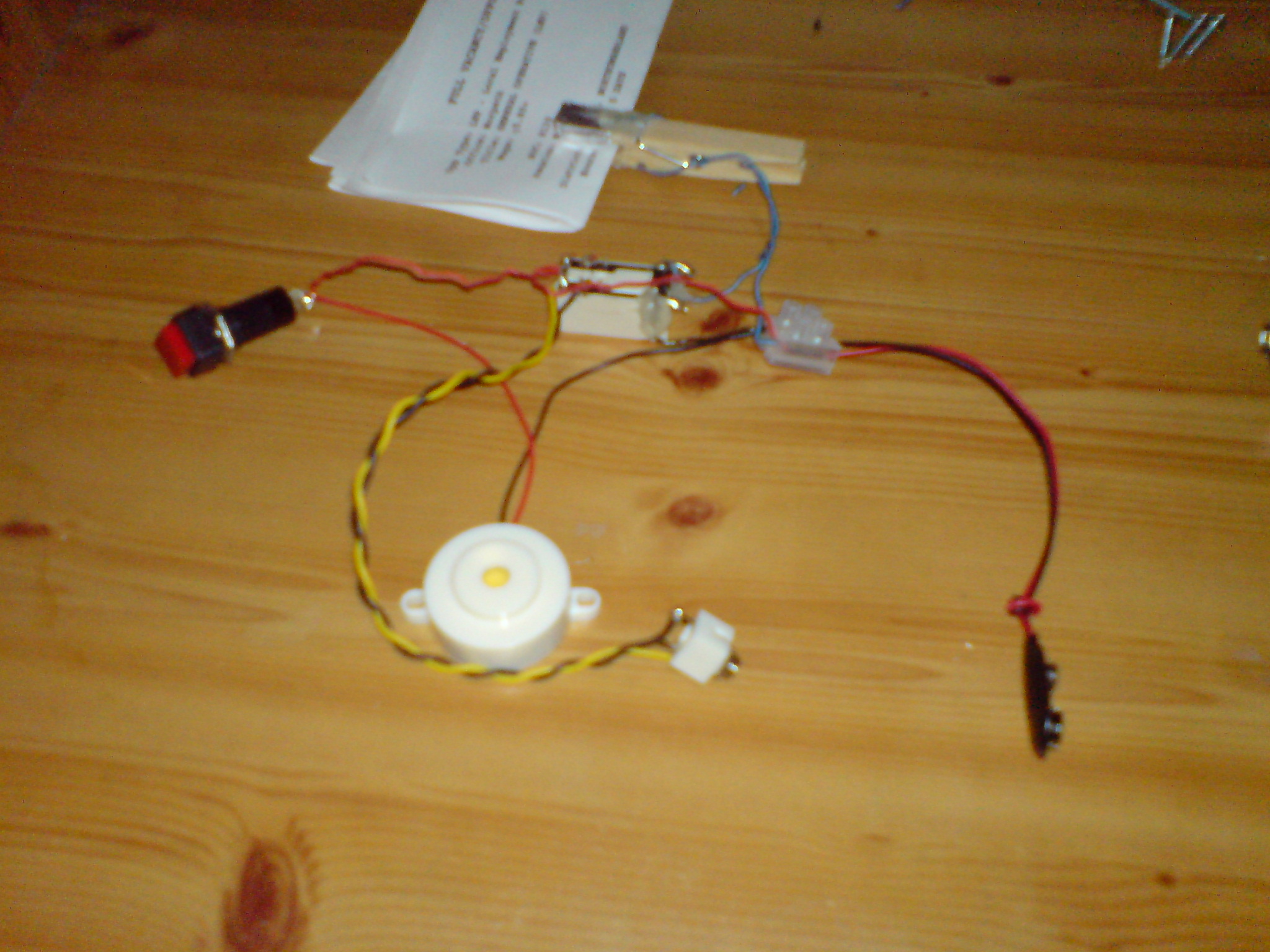
18). Now in the photo above is the finished unit I want to bench test it before you put it into your own case/box connect a Lithium or Alkaline PP3 Battery 9 volts to the battery clip.
19). Now take away the paper you should near the sounder going off if not push the switch on if you hear it then you have done every thing right.
20). Now connect your modified cell phone to the 3.5mm socket and remove the paper now the sounder should be going off and the cell phone should be dialing the prefixed number.
Now how the unit works is very basic when the dog pulls on the Lace this allows the two silver contacts the peg to come together and make a full circuit.
Then the power from the battery energizes the relay coil and switched two small levers from the middle pin to the back pin on the relay so now you can see why we need to solder one wire to the middle pin on both sides of the rely and the same with the back pins.
When the relay is not being energized turned on it is not touching the two back pins this is why the unit does not activate
Now when the unit has been activated the sounder and cell phone will activate at the same time. The sounder can be turned off even if the unit has not been activated but the cell phone can not be turned off as this is a safety devise.
When help arrives some one can push on the on/off switch that will turn the sounder off.