Welcome to this simple Global Remote control by cell phone, Land line the unit is one way but if you used two cell phones and two electronic light kits then you can have an on / off global switch system.
The finished unit has been uploaded to my You Tube page click here to see the video.
I will start off with a simple explanation how the system works is like in the first version of the global remote control: http://www.anthony-dacko.net/Radio-link-1.htm I will use the same idea but in this system I am going to use a latching relay to hold the electrical devise on when it has been activated from a phone call.
I designed this simple unit to allow you to turn on or off an electrical devise from any were in the world just by phoning a mobile phone as soon as you hear the first ring tone you would have activated your electrical devise so the unit cost nothing in call charges no matter where you are in the world.
I will be designing and building more advanced systems that will use DTMF tones also on some of the designs the connections will be very secure when using DTMF tones.
The letters DTMF stand for Double Tone Multi Frequency this is what you hear when you press the keys on your cell phone.
Now the items you will need are below most of the items can be got at very low cost and should be available in most countries around the world.
1). One cell phone any cell phone will do for this project as long as the phones light comes on when it rings.
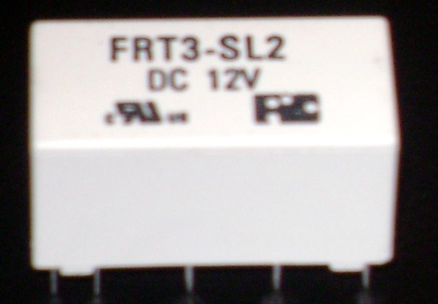
2). One Latching relay see photo above this is a very common latching relay to find on the internet at low cost in the UK order it from Maplin electronics: Here If you are in the USA get it from ebay here: Latching Relay Dual Coil 12 Volt #FRT3 or use ebay in your own country any latching relay will work keep in mind this is for low power switching devises.
3). One small light activated electronic kit form or ready built and tested switch from quasar electronics here: 3079A - Basic Light / Dark Activated Switch They do ship international.
4). One simple push to make switch
get this from any electronic shop or from Bits box order no: Push
Button Red Push to Make switch
Item Number SW056 They do ship international
5). One PP3 9 Volt battery any shop.
6). One PP3 9 Volt Battery Clip or Snap look on ebay in your country or ant electronic shop.
Now we will start to build the project below
5). Now if you have got the light switch in kit form then build it first to keep this as simple as possible we will keep the soldering to a minimum or not at all.
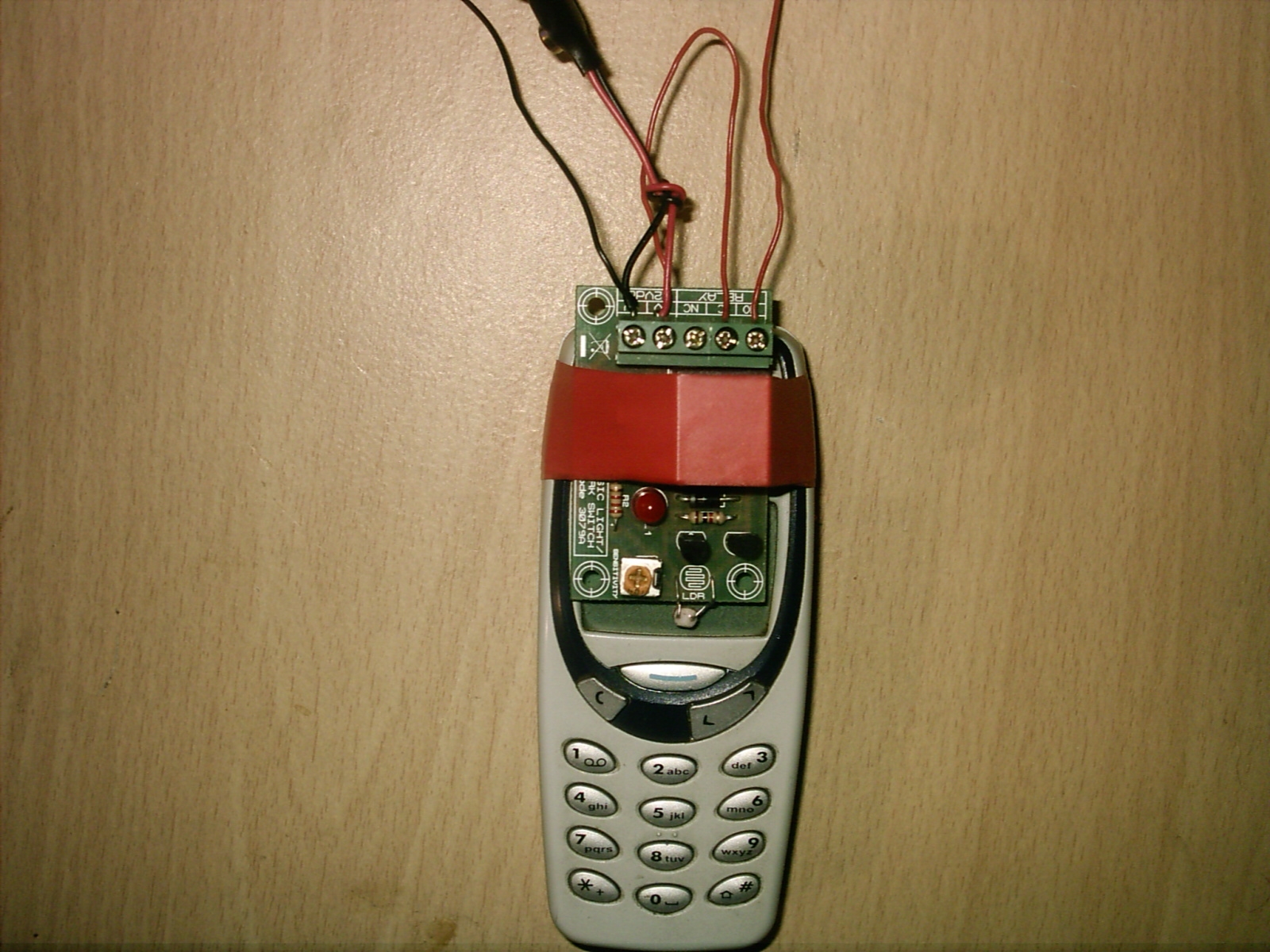
6). Now put your light kit on top of your phone like in the photo below and connect the PP3 Battery clip and Battery also put some PVC tape around the relay to hold the kit onto your mobile phone.
7). Now connect the red wire to the + V of the kit and the black wire to the - V on the kit see photo below remember to take some of the covering off the wires first.
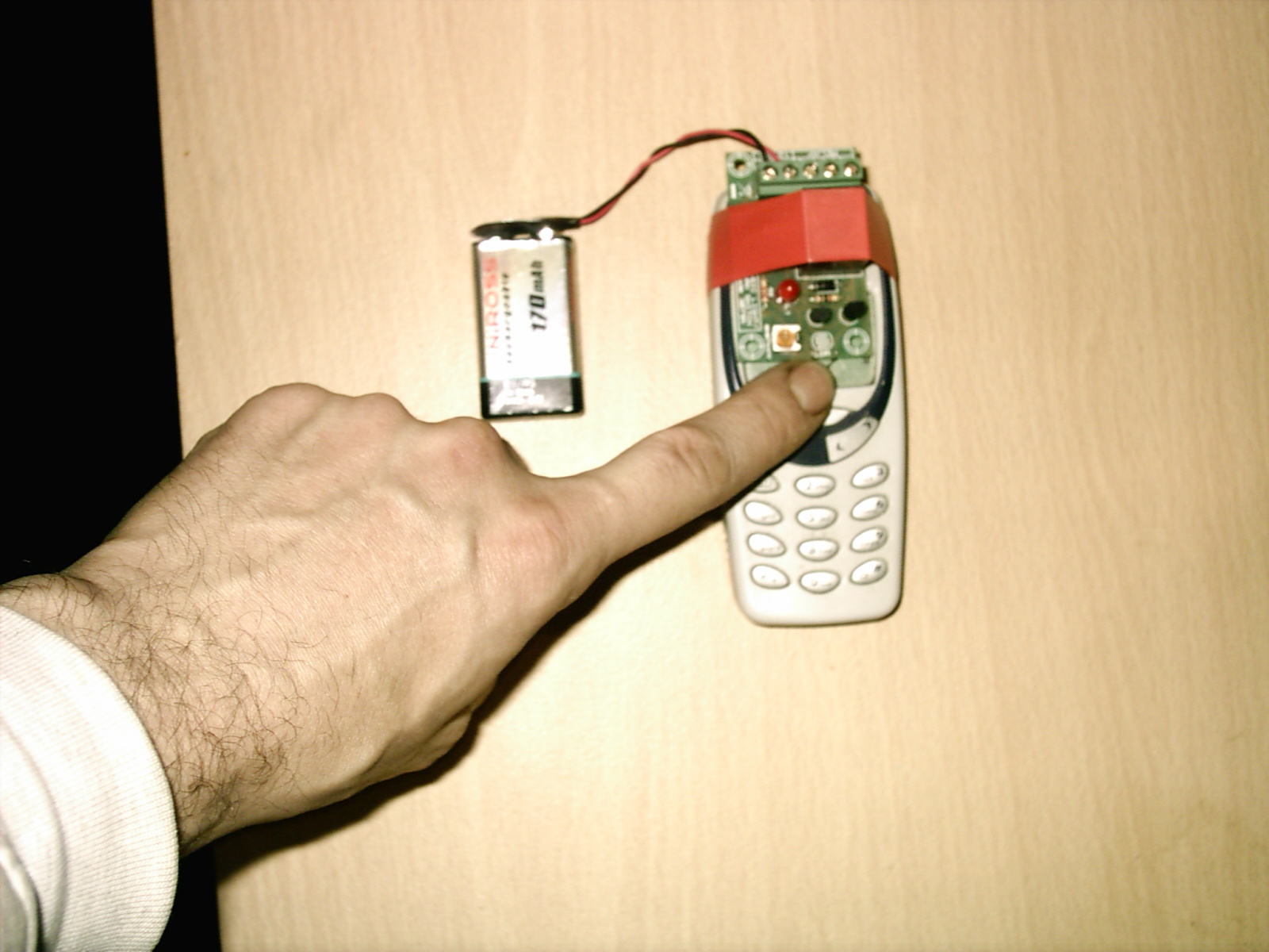
In the photo above I am holding down the LDR Component to stop the kit turning on.
8). On the kit you will see a yellow dial go to a dark place and push on one of the buttons on the mobile phone if the kit turns on and the Red Led light comes on and you hear a click from the relay then this is working fine.
If the LED light did not turn on then turn the dial till it does come on and you should all so hear a click from the relay as it switches over this is the first part of the kit working fine.
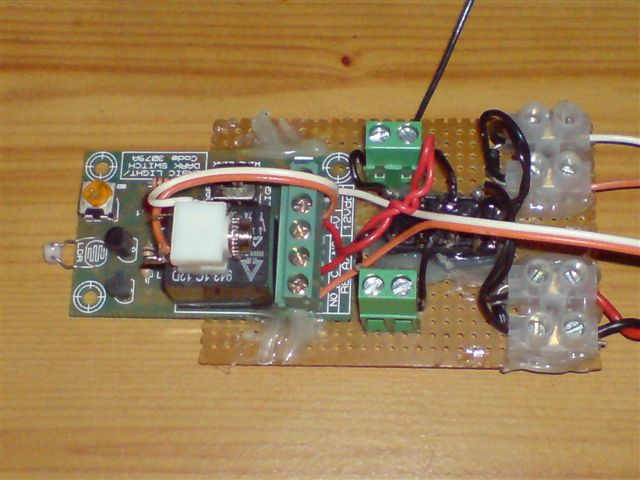
9). Now we will add two wires from the back of the kit connect one wire to the screw down terminal marked NO and one wire to the Screw down terminal C see photo below.
Now that you have attached the two wires to the NO & C Connecters.
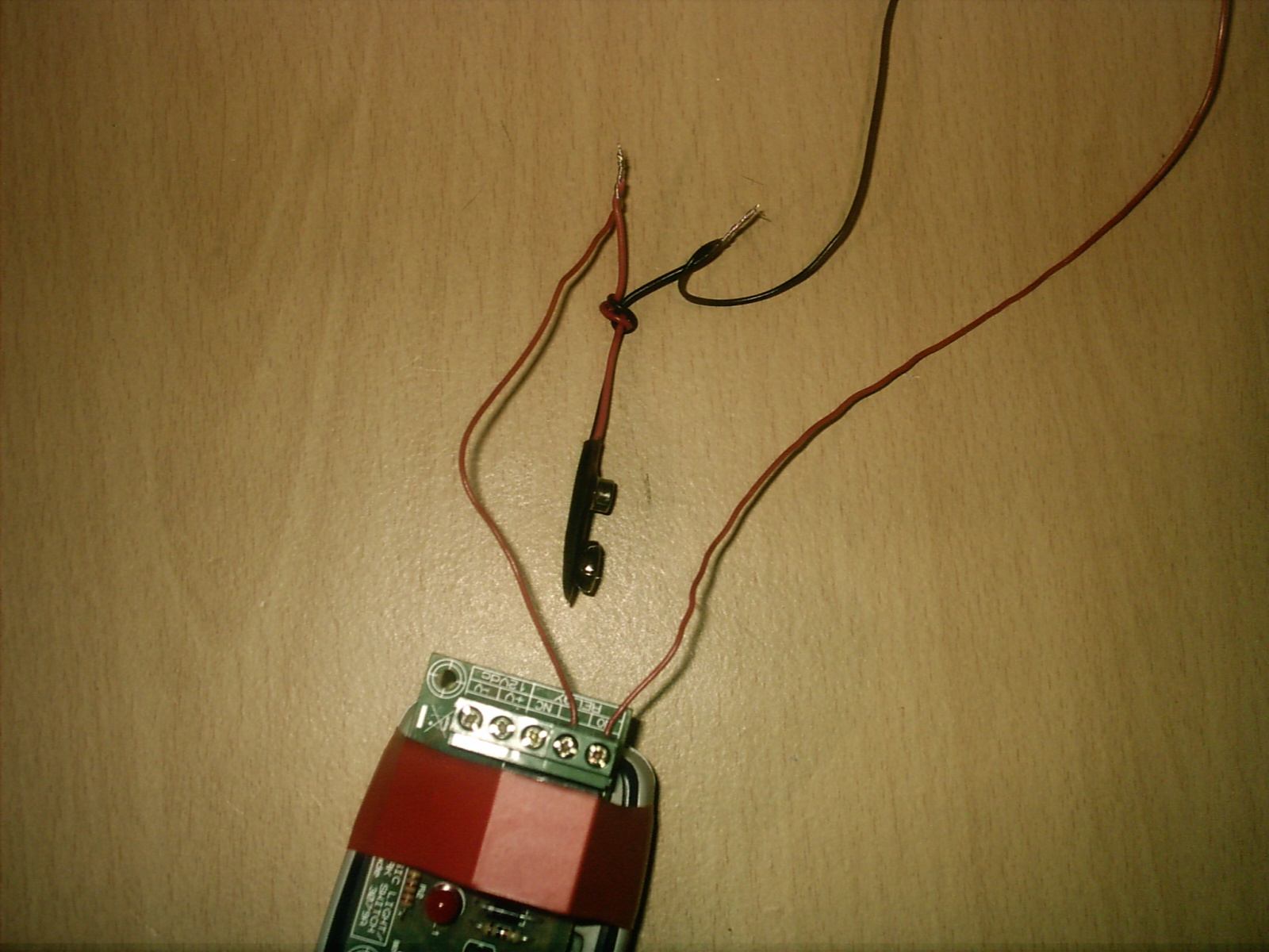
10). When you have connected the two wires from the NO & C terminals the wire coming from the C terminal connect this to the red wire of your battery clip and twist them together now connect a second black wire to the black wire on your Battery clip and do the same as before.
11). Now connect the red wire from your Battery clip to the + V terminal and connect the black wire to the -V terminal see photo below.
Please note the NC terminal is not used here.
12). Now if you have a test meter connect the black long wire to the black test probe and the red long wire to the red test probe connect your battery.
13). Now if your L.E.D. light is on then you should be reading the volts from the battery this wants to be within 8 or more volts see photo below.
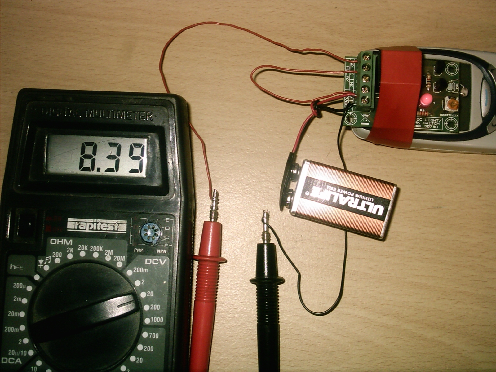
Now as you can see from the test meter it is reading just over 8 volts this is fine all so see the red L.E.D light is on.
14). Now you may be thinking why is the L.E.D light on this is down to the back ground light this is why we need to put the devise in a dark place.