Welcome to the second part of the simple Global Remote control by cell phone or Land line.
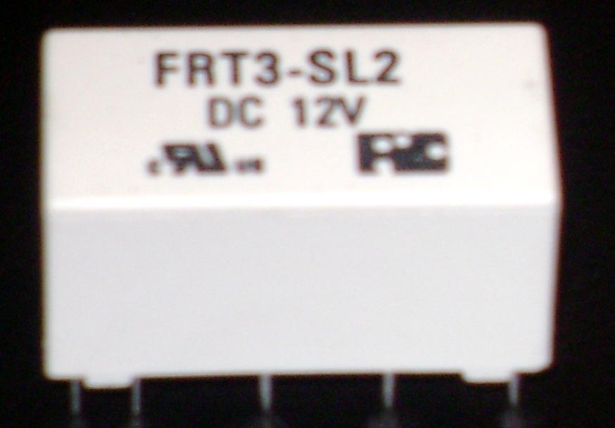
1). The first thing to look at is the latching relay it has 10 pins at the bottom of it two at the front right side and two at the left front side this is the two coils.
2). Now we have 3 pins on both sides left and right side this is the switch over say if I connect a wire to the middle pin and the back pin on the relay right side only this would be called NO Normally Open circuit.
3). Now if I applied power to the first pins on the relay this would Energize the relay this means turn it on now my circuit would go NC Normally Closed circuit and send power to my electrical devise.
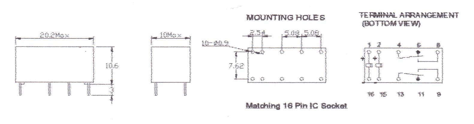
4).Now see the Relays diagram above this shows us how the workings of the relay work unlike normal relays that have only one coil with a latching relay they have two coils so once activated they will stop on until you apply power to the second coil..
Now we will start to look at the construction and how to put the simple GSM global remote control together.
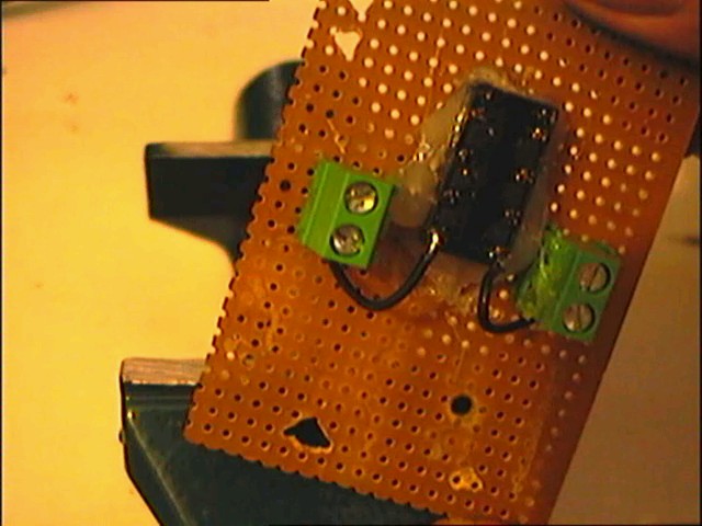
In the photo above I used a hot melt glue gun to hold the Latching relay to the board and added one connecter block to opposed sides solder a wire from the back of the relay pins like in the photo and connect the wire to the end of the connecters see photo below.
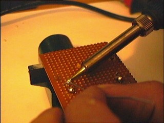
Now in the photo above I have done the same thing but am soldering the bottom of the contacts.
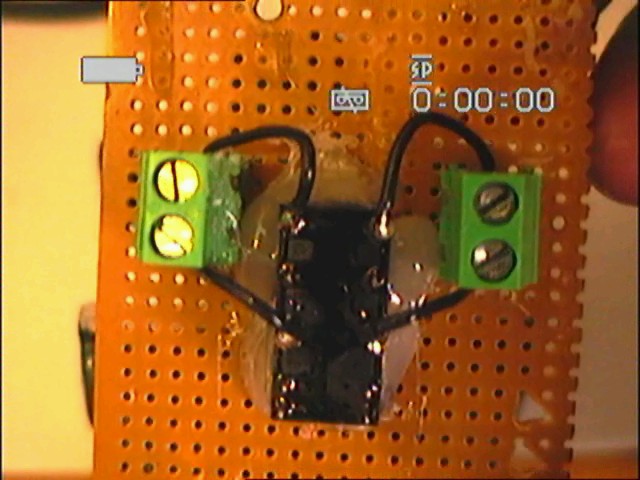
Now in the photo above I used my Camcorder to take the photo connect two wires to the 3rd pins on the relay and solder the ends to the ends of the contacts like before.
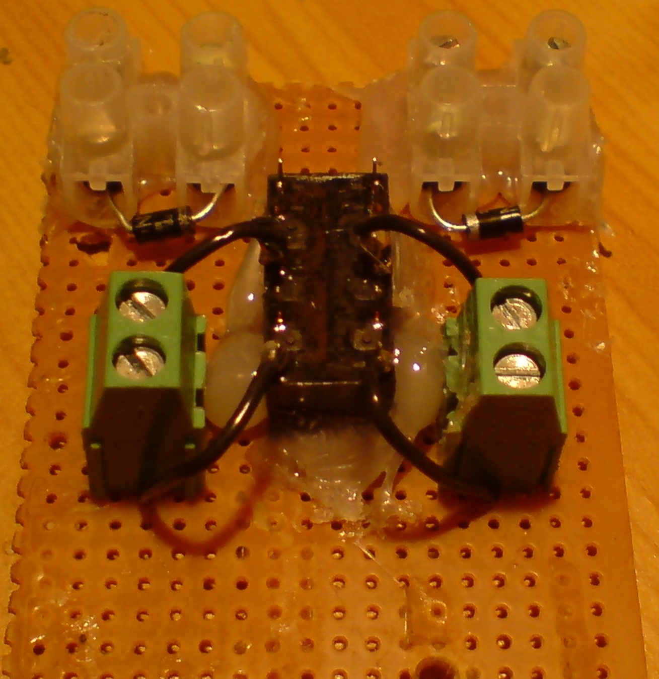
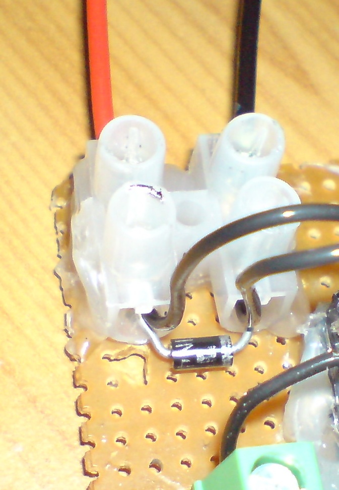
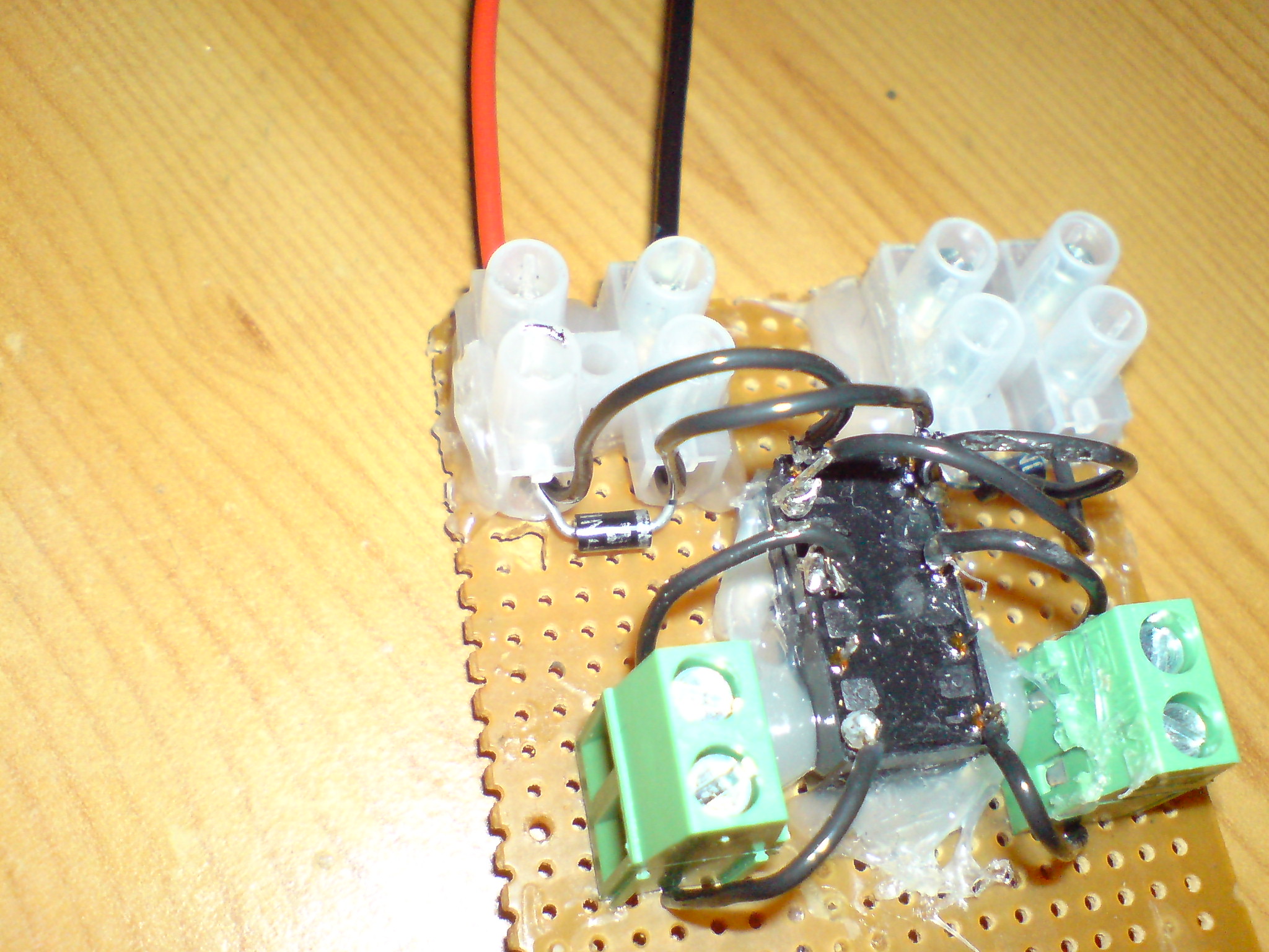
Now in the photo above you can see I have now connected two connecter blocks on to the circuit board and pushed to rectifier diodes 1N4007 in the ends of the connecters this is to protect the coils.
Now in this photo you can see I have soldered two wires to the first relay contacts and pushed the wires in to the left contact block with the diode.
Now in this photo you can see I have soldered the second two relay contact wires and pushed them in the right connecter block with the diode.
In the photo below you can see witch way the diode is facing put the black lead in the front of the silver band on the diode and the red lead to the back of the silver band.
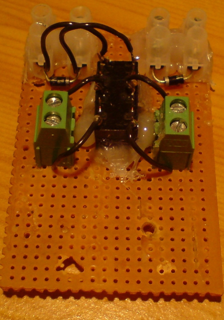
Now in the photo below solder two wires on to the connecter block both sides start with the right side solder one wire to the very back pin of the relay right side then miss one pin and solder the next pin right side then do the same with the left side.
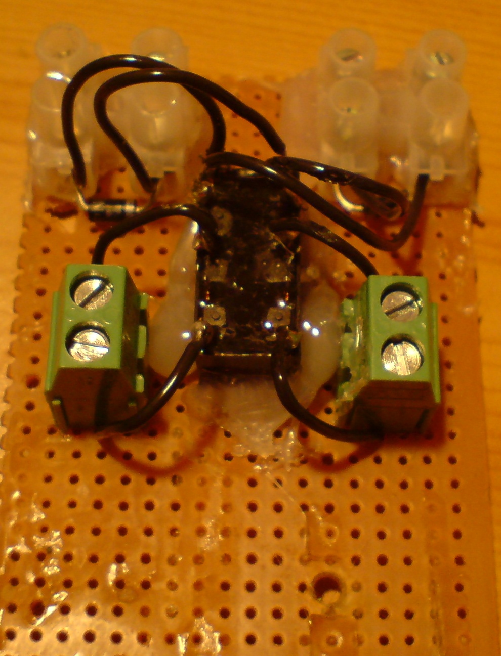
The photo below is of the finished unit
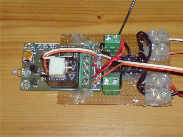
Now all you have to do is connect every thing up and you should if done right have a working remote control that will work with any cell phone.
5). Now why a normal rely will not keep the devise switched on is simple when your mobile phone rings the light comes on using the light circuit kit this will pass electrical current to the relay on the green board and power the relay on the second board.
6). Now Let us look at what happens if the light on the mobile phone goes out then no electric current will pass to the black relay so turning it off and this would turn the second relay of as well.
7). Now we will look at the Latching relay if the phone rings and the light comes on this would turn on the black relay and send power to the second latching relay but as soon as the light from the phone is removed the black relay will turn off and stop powering the second latching relay.
8). Now the second latching relay will stop in the on position as it was turned on by the black relay powering the first contact pins it is being help by a simple magnet this is how they stay on after the power has been removed this is why they get called latching relay to reset this relay back again is simple.
9). Now to reset the latching relay all we do is power the second two pins on the latching relay see photo above two pins are very close to the front of the latching relay.
10). There are a number of ways we can reset the latching relay back to normal one way is with a manual push button or a second cell phone & light circuit.
11). First and what I did here is use a simple push button to reset the latching relay like the power from the green circuit board that sent power to the first two pins on the latching relay we need to send power to the second pins on the latching relay to reset it.
12). In the case of the manual push switch all we are doing is passing an electric current to the second pins and this will energize/turn on the coil and switch it back to normal we use a diode just to pass the current in one direction only.
When you switch on any relay you generate a Magnetic Field called EMF Electro Magnet Field as this is falling it makes an AC signal this signal goes back and forward this is why we use a diode to stop this AC passing in the opposed direction.
13). Now to reset the second latching relay is very simple this will give your project an on / off switch by just phoning the second mobile phone both phone work the same way the first mobile phone and light circuit will turn the phone on the second mobile phone and light circuit will turn it off or reset it ready to be turned back on again.
14). All you have to remember is the first light circuit is to turn the latching relay on and the Second phone powers the second latching relay coil to turn it off/reset both light circuits and phones work in the same way.
Now any problems please give me a bell or e-mail as they say and I will be more that happy to help. Anthony@anthony-dacko.net