Welcome to this page on how to allow a Service dog to get help by
activating the one touch dial of a cell phone also using a smart phones GPS
signal to get the location.
Now if you would like to
see the Devise working then visit my You Tube page here.
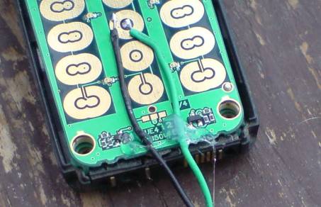
In the above photo you can see it has 3 LED lights on it 2 are
activated every time the cord is pulled by the service dog it helps in location
finding by turning on the lights.
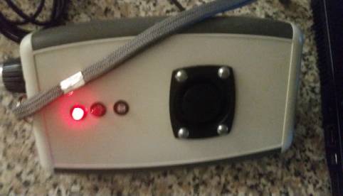
The top Led Light in Red won't switch on when the Cord is pulled
this is only for charging the rechargeable battery see photo below.
The top Led Light in Red won't switch on when the Cord is pulled
this is only for charging the rechargeable battery see photo below.
The middle LED Light comes on every time the cord is pulled from
the devise this is a super bright LED White light for helping to show where the
sound is coming from.
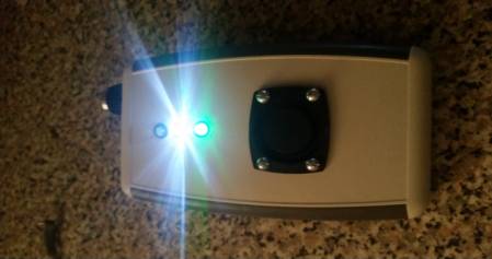
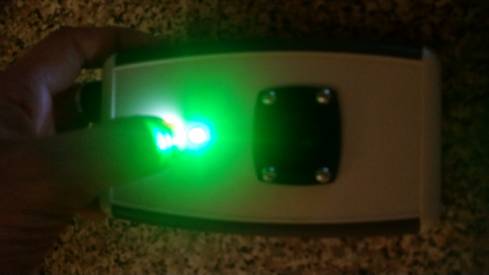
The last LED light in green is to indicate that the internal relay
was activated by glowing green this stops on as long as the relay is still in
the on mode, Even if the battery goes low see photo below.
It is what activates the one touch dial on the modified cell phone
to make the call after the cord is pulled by the service dog the relay will
activate the cell phone and call your mobile this will take about 2 seconds to
activate the cell phone after the cord is pulled
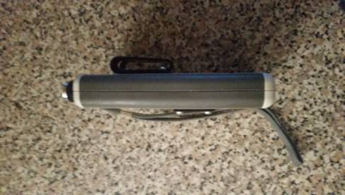
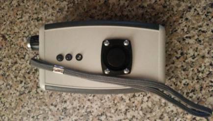
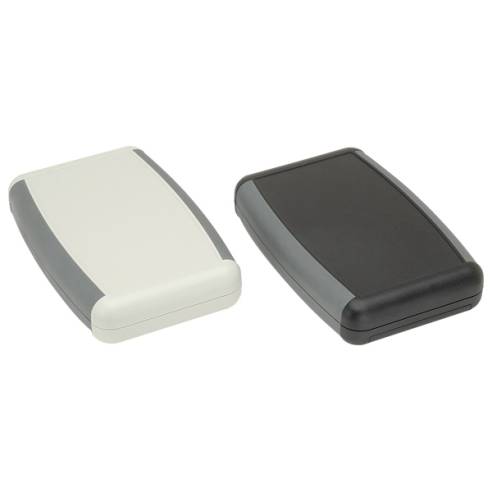
In the side view you can see how slim the case is what case you
use is up to your.
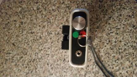
Now this is the top view of the devise you can see the tug alarm
cord and volume control this was a 10K Log type in the photo below.
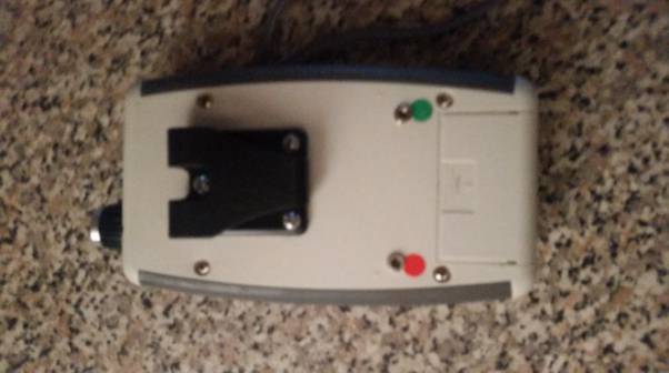
Now this is the back view of the devise the red sticker is the
charging socket of the 3.5mm sockets if you are using a rechargeable battery,
The other 3.5mm socket with the green sticker is for the test meter so I can
test the battery voltage in stead of opening the case at the back.
1) Now in the three Schematics
below I have designed some very effective GSM Tug Alarms when activated with the
help of a Modified cell phone will sound a siren and call the number in the
cell phone just by allowing a service dog to pull on a cord on the devise.
Now all the parts for the three
designs are off the shelf components, I have avoided using any advanced
electronics in the designs also the designs can be built at low cost.
2) Once the service dog pulls on
the GSM cord this will send a signal to a emergency responder by activating the
one touch dial that most cell phones have built in, I am only using older cell
phones with push button keys as this is more effective.
3). Now as soon as the Emergency
responder gets the call showing up on there own mobile screen the name for the
number could be some thing like Seizures or Diabetes or similar, Then they will
know it is the service dog that has activated the GSM tug alarm.
4). I have done three schematics
below any one with a back ground in electronics should have no problem building
the simple designed below.
5). The three designs below can be build for low cost and could even save
life's for people living with Epilepsy, Diabetes and so on if they have a
service dog that is trained to pull on the simple cord on the device.
6). Now using a smart phone all
smart phones have built in lost or stolen tracking apps that tell you the
location of the cell phone if it is lost, We can take advantage of the GPS
signal as you don't need to loss your phone to use the Tracking GPS apps.
7). Once the service dog
activates the GSM tug alarm that will send a signal to the emergency
transponder then they will need to know the location of the cell phone so they
can look on a Mobile phone, Computer, Tablet with cell phone capabilities or
just turn on the Wi-Fi hot spot on a smart phone.
8). Please note I am covering
Android smart phones here but any other smart phone will have a app that lets
you get the location of the smart phone.
It could be a (I phone) (Android Phone) (Black Berry
phone) (Windows Phone)
-----------------------------------------------------------------------------------------------------------------------------------------------------
9). This is for Android smart
phone users first you will need to sign up for a free Gmail account at www.gmail.com after
you have signed up go to the down load page on your smart phone down load the
free app here.
10). One you have down loaded the
free app on to your smart phone go to www.androidlost.com Please keep in Mind the Android Lost page is
in BETA test version. Now
sign in with your G-mail details then you should get a message on the Android
lost site telling you every thing is set up ok see photo below..
11). Now why you are still logged in to the Android lost page
click on Control at the
top of the page go down
to Location click on it this will send a signal from goggle
servers to your smart phone, If every thing is working fine with the goggle
servers you should get a location GPS goggle map of the location and a accuracy
score of the smart phones Location see photo below.
In the photo below I used GPS to find my location but have found
that even so it finds my location very quick and well it also Scan's near by
Wi-Fi towers as well Accuracy in Meters unlike other GPS devises using a smart
phone gives you more control over your devise.

When you get the location you can click on the View Interactive
Map on the link to get a better location of the area or see the area using
Goggle maps will let you drive, walk, or go by bus with a map giving you
directions telling you which way to turn.
The more updated your Smart
phone OS the better I used a Samsung Galaxy 5 with Android Lollipop 5.0.1
In the photo below it gives you a very simple map to follow with
Directions Or you could opt for the turn right or left option see photo below.
In the photo above you can see how simple the directions are all
you have to do is put in your area you are in at the time of Travelling and it
works it all out for you are in the right area when travelling see photo below.
Now in the map below I have taken a
Satellite view of the area.
Now we will look at the Construction I am
only going to give a simple design here as if you want to add more to your own
design then you can add it as you go along this saves me adding more to it.
For the tug alarm clip just use a cheap tug alarm clip and
connecter from an old tug alarm.
Any old cell phone with push buttons and one touch dial on it like
Nokia 1208.
Cell phone opening kit look on Ebay.
Relay can be any 12 volt type that will fit in your case.
Resisters depending on the design you want to build.
LEDs
Diodes 1N4001.
Electric Drill for drilling the holes.
3.5mm sockets and 3.5mm plugs and cable.
LM 7805 Regulator.
100UF 16 volts.
5 Volt relay.
Plastic case any type you like look on Ebay or your local
electronic store or shop
Look for the one with the battery compartment on there web site http://www.spiratronics.com/
Case use in Prototype can be got from spiratronics spiratronics
Unit 2,
Pinnacle Close
Crowland
Peterborough
Lincolnshire
PE6 0GB
United
Kingdom
Tug alarm I used in the prototype was this one below not all tug
alarms will have the right clip this one can be removed very easy for this
project.

Battery clip PP3 type.
Making the round hole in the plastic case use a Cone drill or a
hole saw most DIY shops or Ebay.
Now for the sounder I just used a old siren front case as the tug
alarm needs to be kept dry see photo below.
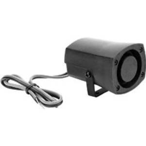
Take off the front cover of the siren look for the ones with 4
screws in the front panel.
Now as you can see I have taken off the front panel and will use
this for my sounder, You could also use the electronics from the siren if your
case allows it.
Now we will look at the Schematics this is just a basic one for
the simple design.
Now if your using a 5 Volt relay then use this design below.
Now if your using a 12 volt relay then use this design below.
Now in the Schermatic Diagram below I have added an External out
put from the tug alarm so when the Clip is pulled out this can power add on 9
volt devises as well. Now in the Schematic below I have designed this one the same as
above but used a regulator so when the cable is pulled it will allow you to
power other devises connected to your tug alarm out put 5 volts or 3 volts
depending on what voltage regulator you use. 
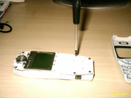
Now in the photo below once you have opened your cell phone make
sure you have one touch dial turned on and the Sim card is set for the number
button on your mobile that will call you when the relay closes.
How to modify any one touch/speed dial cell phone
below.
Now you have all the things you
need to modify your cell phone first we will need to load the mobile number in
to the phone make sure you have the ringer set to silent all so one touch answer turned off and one touch dial or speed dial turned on.
It would be best to send the
signal to a back-up mobile phone when activated as they have caller display on
them.
Now say if you put your own
mobile phone number into number 5 and connected the wire's coming from the
relay to number five this number locked into the phone will be called as soon
as the relay closes within 2 or 3 Seconds.
Now I will open my own cell phone
after you have opened yours and taken out the screws you may see some thing
like this as you can see from the photo below all phones have copper pads this
is where we will solder our two wires from the relay if you have loaded your
own mobile number in all from 2 to 9 then any one pads will allow you two
connect the wire from number 2,3,4,5,6,7,8,9 pads.
In the photo above you can see the phone with case off
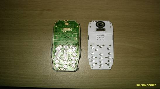
In the photo above you can see how the phone buttons work the
white plastic card is covered with silver buttons this is carbon and is what
makes the connection to the pads to put the numbers on your screen we don't
need this now.
Now you will need to tin the two
wires before you solder them to the circuit board to do this take off the cover
from the wires and very carefully solder the two wires this is called tinning
we do this so it is much easer to put the two wires on to the pads.
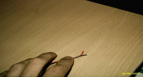
The wire in the photo above has been tined and cut short as I used
wire with red and black there is no need to do this speaker wire will work
fine.
Now look at the pads you have an
inside pad and outside pad solder one wire to the inside pad be careful the
inside pad does not touch the out side pad and VS or you will get a short or
bridge and you will need to use cleaning tools to try and fix it. .
Now when you come to fix your
wires to the pad put one wire in side the pad and using your soldering Iron
push down on the wire this will heat the solder so it fixes to the pad do the same
with the next bit of wire but connect this to the outside pad.
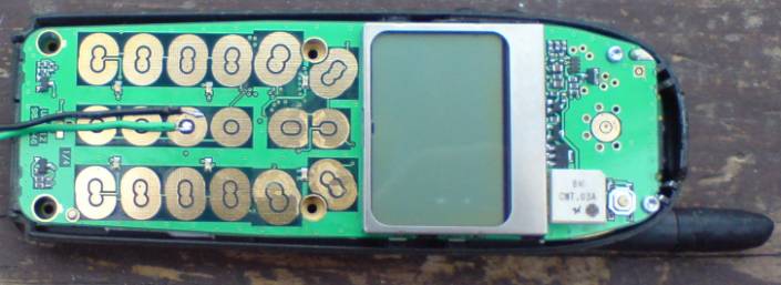
In the photo above you can see I have soldered the two wires to
the in & out side pads of the modified phone in the photo above I used my
Nokia phone as this was a better photo than the one I used before.
You may also want to add a little bit of hot melt glue to the
bottom of the wires to take some of the stress from the solder contacts see
photo below.
Any phone with speed dial will work.
If you need any help please e-mail me at anthony517654@gmail.com