Welcome to this simple modification to the Service Dog GSM Activating unit.
Please note if you have come to this page from a search engine click here.
Now if you would like to see the unit working visit my You Tube Page here.
1). On this simple page I have added a small test button to the side of the Service Dog GSM Activating unit. This test button will allow a person to test the unit with out removing the lace this allows them to check the system is working ok.
2). This can be helpful if you would like to test the unit with out removing the lace from the unit all you will need to do is press the button in for about two seconds and your phone should dial the pre-fixed number.
3). The unit will work the same when the Service Dog pulls the lace from the unit your cell phone will call the pre-fixed number.
One Push to make contact switch 2
contact configurations. 7mm mounting hole.
Momentary acting contacts.
Items you will need one small Push to Make Switch you can get this from any electronic shop or try Ebay in your own country or order it from Bitsbox here. they do ship international.
4). The unit works by using a small Push to make contact switch wired to the same 3.5mm socket the peg is wired to when the push button is not pushed in there is no electrical contact so the unit is only activated when the dog removes the lace from the unit.
5). Now when the lace is still in the unit and you press the push to make button in this by-passes the Pegs contacts and activates the Cell phone.
6). Now when you let go of the push button the switch goes back to normal and the lace is ready to activate the cell phone.
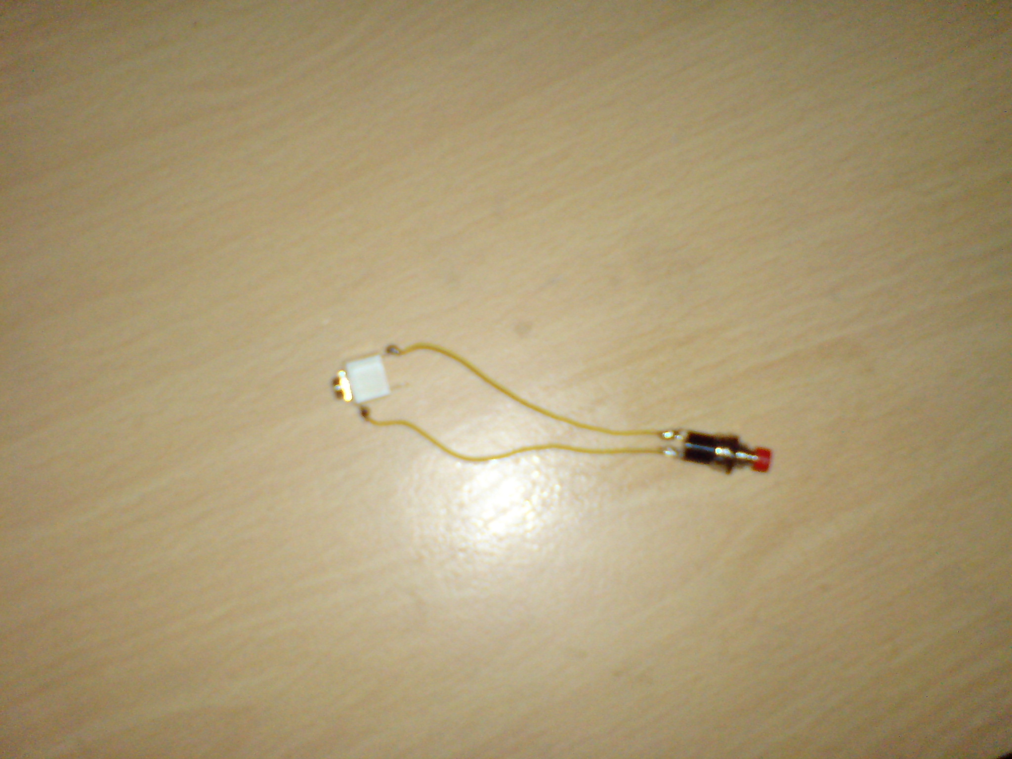
7). Now we will look at fixing the switch to the unit but first we need to tin our wires see photo above I have taken off some of the covering from the wires at both ends put your soldering iron on the wire and put solder on to the bare wire and move it slowly across the bare wire this is called tinning.
Why we need to tin wires is so they do not come apart so all you have to do is twist the bare wires and then solder them so your ends should look like the one is the photo above.
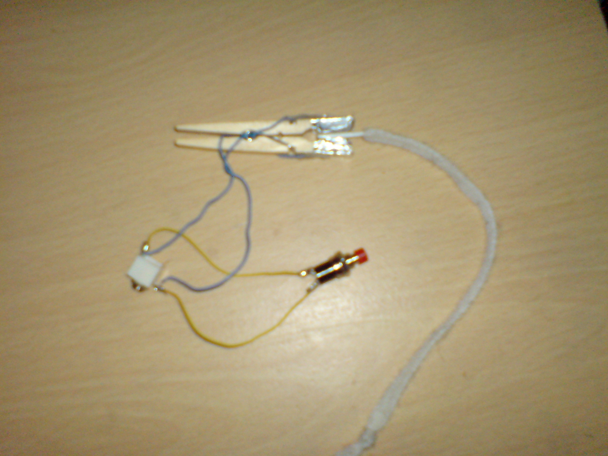
8). In the photo below you can see I have Now soldered my two wires to my Push to make switch on this switch the button is red but on the unit it is black.
9). In the photo below you can see I have soldered my simple switch to the 3.5mm socket Top and Bottom contacts.
10). Now you will need to solder the two wires coming from your peg to the same contact wires on the 3.5mm socket see photo below.
11). Now when you have done all this make the holes in the case and put your unit in the box please note you don't have to have the test switch if you don't want it the unit will work fine with out it.