 This unit can
be operated from a cell phone from any where in the World.
This unit can
be operated from a cell phone from any where in the World. Welcome to this page on how to build a simple Cell phone to Cell phone remote Control from 1 to 8 Relay Channels.
This unit can
be operated from a cell phone from any where in the World.

Now if you would like to see the above project working them visit my You Tube page here.
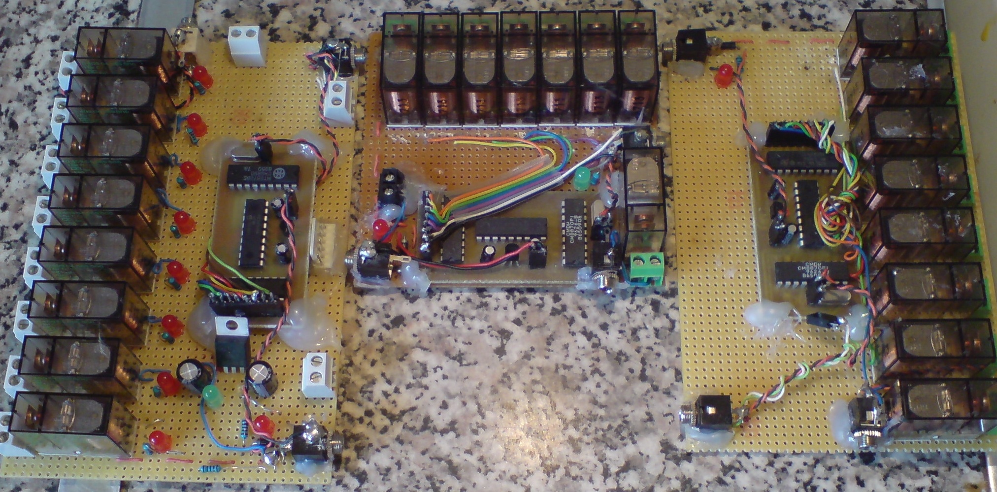
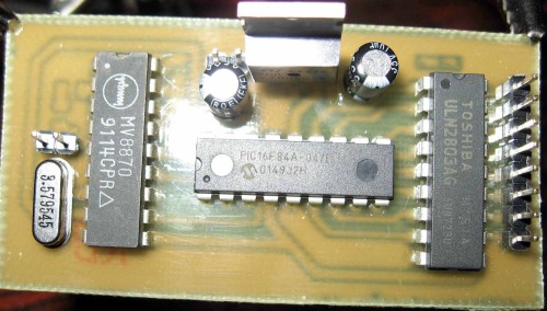
DTMF LED Flashing when Decoding tones uses 8870 chip.
 1). Why I set this simple page up is
down to the amount of cell phones in use today and the benefits of using a cell
phone for remote control of electronic or electrical devises from any where in
the world.
1). Why I set this simple page up is
down to the amount of cell phones in use today and the benefits of using a cell
phone for remote control of electronic or electrical devises from any where in
the world.
2). I will be following on from my
first version that used a land line to operate the relays in this version we
will be building a simple 1 to 8 channel remote control unit that you will be
able to turn on or off your devises from a cell phone from any where in the
world.
3). The benefits are the unit can be
used any where there is no Land line you just need a cell phone signal to makes
the unit portable it can be used with a Pay as You Go Sim
Card so no need to pay line rental.
The unit can be used in the home, office, car, boat, caravan you could even use it on top of a hill for remote control devises it can be used in the middle of a field range is unlimited you just need a cell phone signal for the unit to work and power supply.
4). The unit is
small and will run off any 12 volt power supply this can be a car battery or
Power adapter plugged into the mains unit or even a power generator unit.
5). I don't expect
every one to have a back ground in electronics so to benefit people that are beginners
I have used a ready programmed DTMF decoder this all so helps keep the cost
down.
6). I will be modifying
the unit to work with a stand a lone answer phone as well so you have to forms
of communication to the DTMF decoder.
Now we will look at the items you will need and where to get them at low cost.
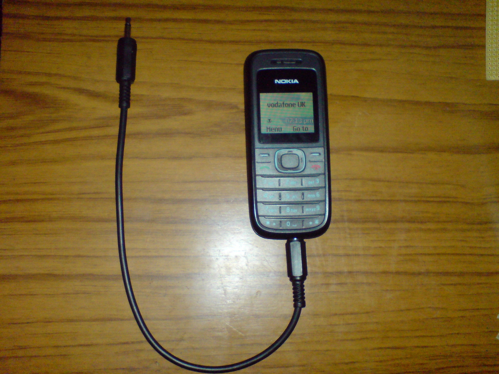
7). You will need one auto answer
cell phone I have used the Nokia 1208 as this works fine for this project I
would recommend this as I give the pin out for the phone this phone has 4 pin
outs but it works fine with just a mono plug connected to the cell phone UK
Click Here or if you live in the USA
click here.
I tested two cell phones with DTMF Tones that worked well one was the Nokia 3310 Mobile phone & the Samsung SGH-D500 Mobile phone.
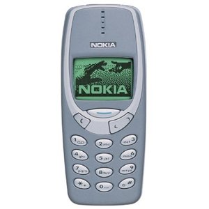
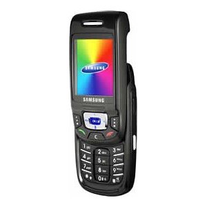
Nokia 3310 Mobile. Samsung SGH-D500.
8). You will need one ready built
and Programmed DTMF Decoder Unit I used the JPL 955 unit Click
here. They do ship international.
Now if you would like to do your own unit I can recommend the following DTMF kits:
CS Tech DTMF decoder kit with 6 outputs, serial (RS232 compatible) & Morse transponder Click here.
Ramsey Electronics: TT 7 DTMF Unit Click here.
In this project I will be using the ready built JPL 955 unit as I want to make this project as simple as possible for people to follow also the Pic chip is already programmed.
9). 12 Volt power
supply this can be a car battery or Power adapter for the mains unit.
 OR
OR 
10). One mono jack
plug 3.5mm and one mono Jack plug 2.5mm Click
here bits box do ship International.

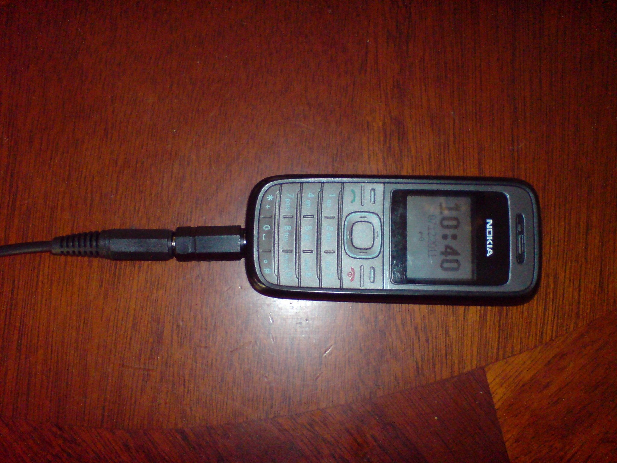
You could use a mono 2.5mm to 3.5mm adapter jack plug see photo below this plug can be plugged in to the Nokia 1208 mobile phone and a mono or stereo cable plugged in to the back of the 2.5mm jack plug.
UK only Order this 2.5mm to 3.5mm jack adapter from Maplin here or order it on Ebay in your own country.
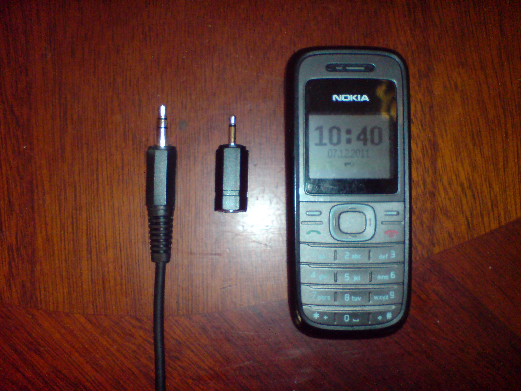
Here is the photo below of the plug and cable a mono or stereo cable can be used with this adapter jack plug.
You could use a 2.5mm jack plug with cable see photo below order it from the address below.
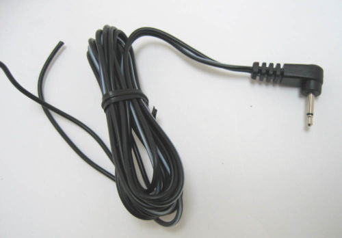
In Car Technologies, 2 Leigham
units
Silverton Rd, Matford Pk,
Exeter
Devon
EX2 8HY
United Kingdom
Phone: 01392|829435
Email: accounts@incartec.co.uk
11). Two 3.5mm Jack
plug sockets this is one for the power supply and one for the cell phone to fix
to Click here.

12). You will need
Relays 12 volt coil any thing from 1 to 8 with the right current ration for your
application you what to turn on or off I used 10 Amps at 240 volts single pole
switching contacts. You can get the relays I used in my prototype from here
order code RLYSPDT10A
Miniature 10A SPDT Relay Click
here.

13). One sheet of
Matrix Board 127 x 95mm without copper strips. see photo below Click
here.

14).
1 to 8 connecter bocks for relays contacts 2-way PCB mount terminal connector.
5mm pin pitch 10A rated see photo below. Click
here.

15).
Now if you would like a LED Light Emitting Diode to come on when your relays
switches on you can get a 5 mm red led RED
65mcd 2.1Vf Ifmax=20mA 45deg: Click
here. or Look on Ebay.
![]()
Please note the units works fine with or with out the LED this is just to show the relays that are turned on it is more cosmetic than any thing.
16). You will need 1K ohms resister if you use the LED this is to limit the current to the LEDs 1K metal film resistor Click here.

Please note if you use one relay then you only need one resister if you use more relays then you will need a resister for every relay you use.
Now if you do not use any LEDs in your project then you do not need any resisters.
Now on the following page we will start to connect our project together